Supermicro SYS-112C-TN Internal Hardware Overview
Behind the storage, we are going to work from front to rear.
One can see the MCIO cables routed through the chassis to the backplane.
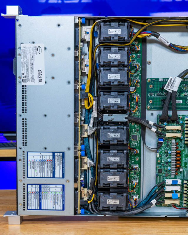
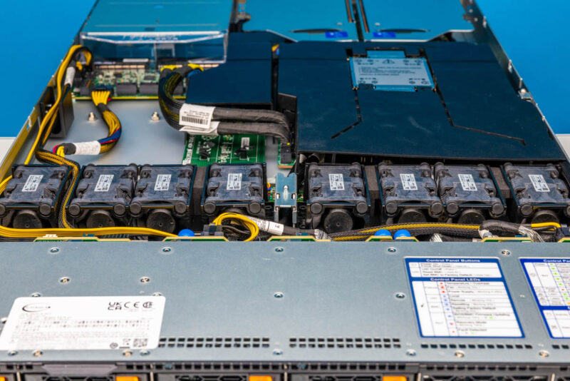
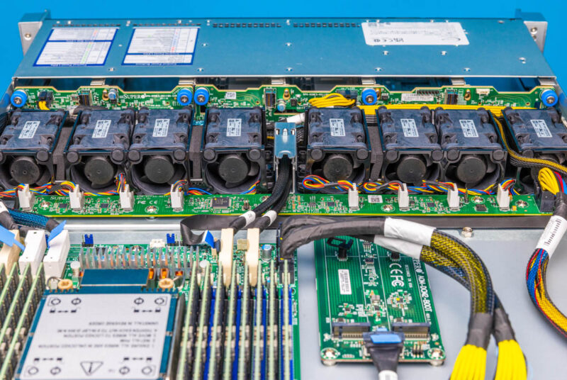
The fans are interesting. Hot swap in 1U chassis is generally tough and, unlike in 2U chassis, hot swap fans are much less common. One can remove individual fans, or quickly remove the entire fan partition.
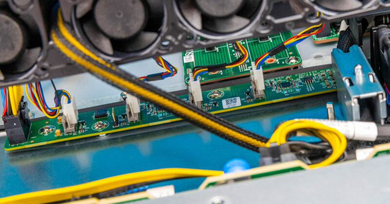
Those fans then connect to a fan control board.
Behind the fans, there are airflow guides. This is a somewhat fun design since you can see the heatsink in the design and the heatsink is an anchor point for the large airflow guide.
Under that airflow guide, we can see the front MCIO x8 connectors.

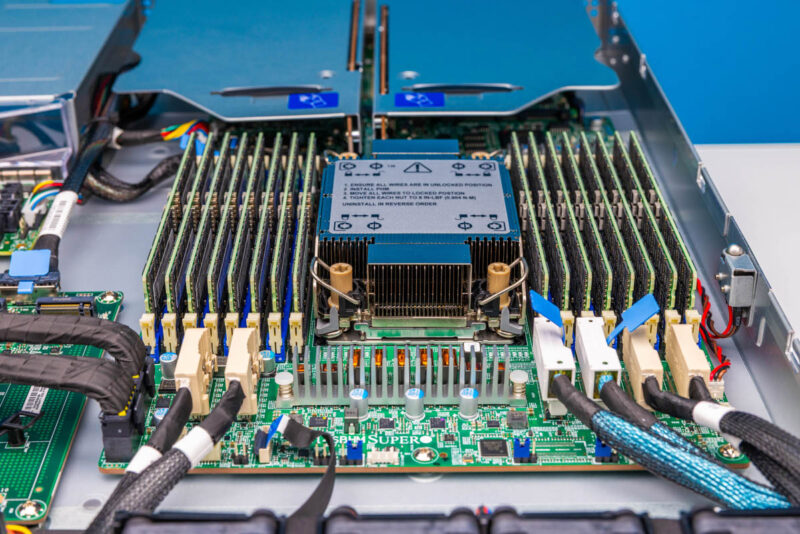
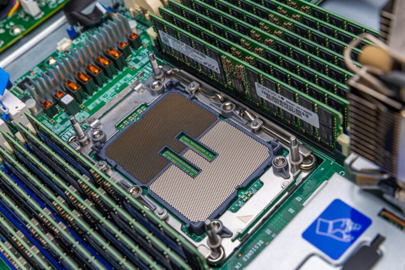
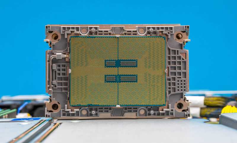
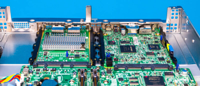
In our system, we have an Intel Xeon 6781P, which is a performance core CPU.
The socket, however supports more than that, either supporting Xeon 6700P/ 6500P or the Xeon 6700E series. One has the option for up to 86 P-cores or 144 E-cores in this form factor. Something we should mention, especially on the P-core side is that Intel has begun to take the 1P market mroe seriously, so the 1P CPUs are priced rather attractively for R1S (single socket) platforms like this.
Here is a quick look at the CPU in the heatsink carrier.
Since we have not covered it in some time, that little lever is the TIM Breaker, or the thermal interface material (TIM) breaker lever where one can lift it and break the adhesion that forms with thermal paste and the heatsink/ CPU.
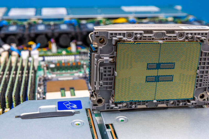
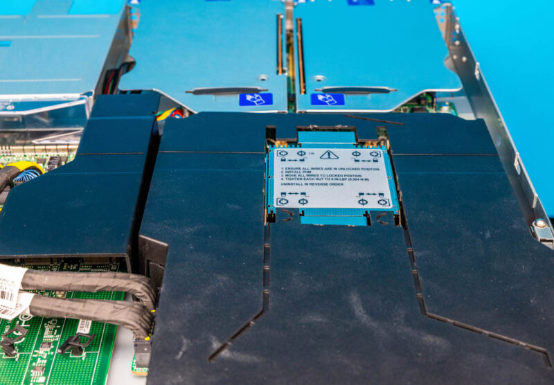
Around the socket is the 8-channel DDR5 configuration with 2 DIMMs per channel (2DPC) for a total of 16 DIMMs.
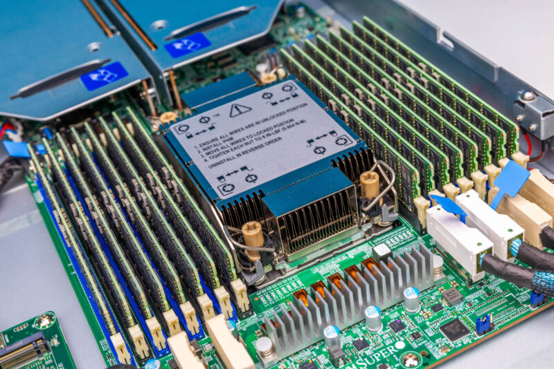
We are going to talk about this later in the topology section, but the motherboard is very small extending roughly twice the length of the CPU socket and DIMM slots. Gone are the days of huge single socket motherboards.
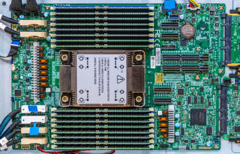
A big part of that is due to the M-XIO PCIe Gen5 x16 riser slots, rear NIC and DC-MHS slots, and the MCIO connectors around the board.
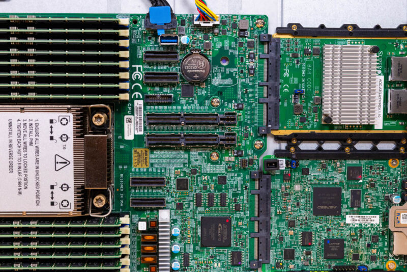
In the rear, we have the DC-MHS board for management as well as the OCP NIC 3.0 / Supermicro AIOM slot for networking. This is a Supermicro CloudDC server so it is heavily inspired by OCP design principles while also fitting in a standard 19″ rack form factor.
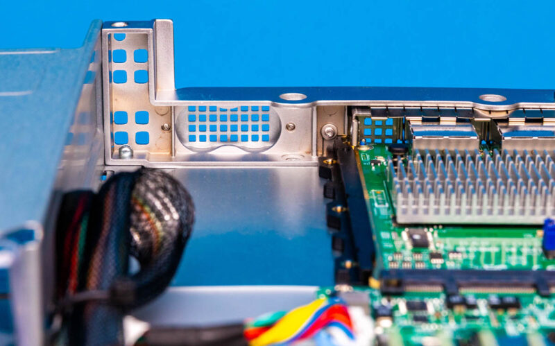
In the rear, we also have a little cutout for liquid cooled applications.
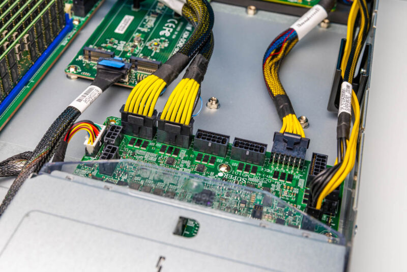
The power supplies feed a power distribution board.
This power distribution board has a number of connectors to power the various systems but also handles the redundancy function of the power supply.
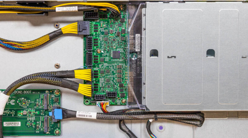
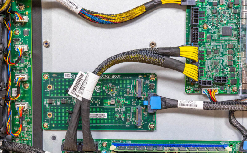
Between the fan partition and the power distribution board is something really neat. There is an area for internal expansion.
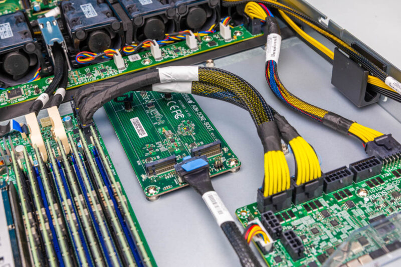
In this system, there is a dual M.2 boot SSD board that is cabled to the motherboard. That is just a cool way to add internal M.2 SSDs.
Next, let us get to the block diagram and topology.


That server looks fun! I would love to see a birds eye view of the server.
Everything seems so small.
It’s not good old SM anymore, but some super-proprietary Dell/hp-like weird overpriced systems. It all started with that disgusting “To maintain quality and integrity, this product is sold only as a completely-assembled system”.
What’s going on with all the USB 2.0 in the block diagram? It looks like USB is routed through the DC-SCM for management, and then broken out to each of the MCIO connectors. I don’t even see a USB host controller coming out of the Intel SOC. This seems like a major shift, my guess is that USB 2.0 is being used as a control plane for CPLD and similar devices.
For a new system I feel like I’d be looking at SSG-122B-NE316R or ASG-1115S-NE316R with 16 EDSSD drives, instead of just 12 older 2.5″.
@Iaroslav – actually, this system isn’t proprietary. its the new DC-MHS form factor.