Supermicro AS-1024US-TRT Internal Overview
Inside the system, we have a fairly standard Supermicro “Ultra” server layout. Behind the storage backplane, we have fans, the CPU and memory, then the I/O and power supplies of the server. We are going to quickly note here that the design of this server is such that the motherboard is effectively shared with the 2U variants. This is important and is similar to what other top-tier OEMs do since it increases volumes which increases quality. Further, it allows the electrical motherboard platform to be qualified in an environment and then a chassis size and features to be crafted around that base building block.
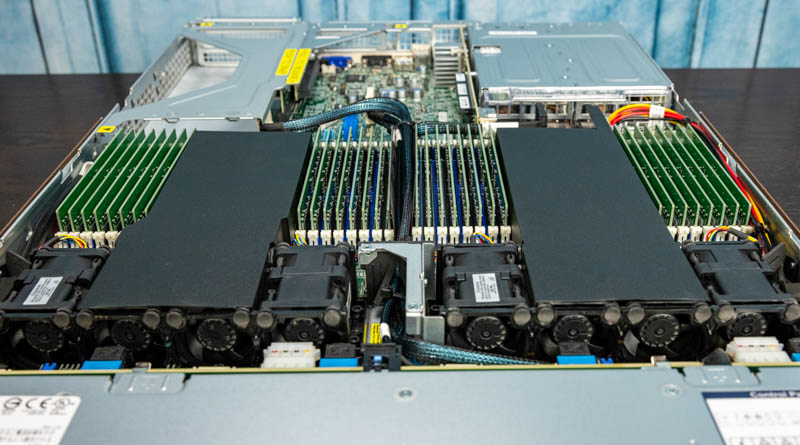
Airflow through the server is provided by eight sets of counter-rotating fans. This helps provide redundancy and cooling capacity as CPU TDPs and the TDPs of other components in a server rise. Fans have had to get better to stay efficient and reliable while also pushing more air through a server.
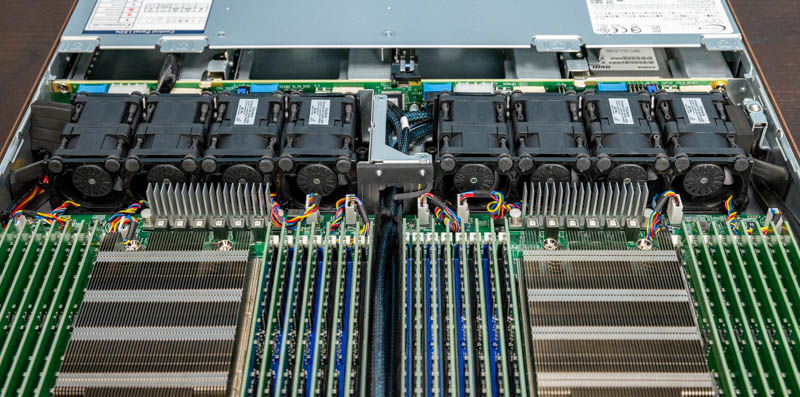
The CPUs are two AMD EPYC 7003 CPUs. In our system, we have dual AMD EPYC 7713 64-core / 128-thread processors for 128 cores/ 256 threads total. This is an enormous jump over previous generations of Xeon parts and is also significantly more than Intel’s top-end 40-core Ice Lake Xeon chip. The server can support EPYC 7002 series and lower-end EPYC 7003 series CPUs as well. For higher-power processors, Supermicro can support them in the system but the configurations over 225W need to be validated.
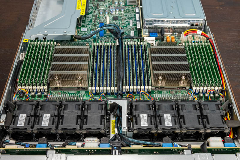
In terms of memory, the processors each have 8-channel memory and can support two DIMMs per channel (2DPC.) That means each processor can support up to 16x 256GB DIMMs for 4TB per socket. In a two-socket server, one gets 8TB of memory capacity.
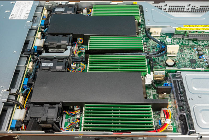
Hopefully, these images show why the motherboard is a proprietary form factor. This is not just a Supermicro design moving away from smaller standards such as ATX and EATX servers. It is driven by the physical width of modern CPU sockets, cooling solutions, and having 32 DIMM slots in a system. Physically, a full CPU and memory configuration, as one would expect in this Ultra-style server, fills almost the entire width of the chassis. As a result, older and smaller form factors, such as EATX, are too small to handle these newer platforms. Supermicro still sells those solutions, but they are not in this class of server because the company uses this as a more full-featured platform.
Another impact of the custom form factor motherboard is that the power supplies are hooked into the motherboard directly, not through a power distribution board. Power distribution boards add a failure point and can be unreliable, so eliminating those boards and associated wiring is a major reason that we are seeing more high-end servers with custom form factors.
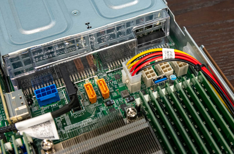
One will notice that we have an interesting set of connectivity between the CPU and PSUs. There are two “gold” SATA ports that can support powered SATADOMs without connecting the power cable. We prefer port-powered SATADOMs because they are easier to work with. There is also an internal USB 3.0 Type-A header in this area.
Another key feature of this segment is simply the GPU power connector and other power headers. In this class of servers, supporting higher-end features such as GPU compute, FPGAs, DPUs, or other higher-end configurations is expected. As such, power is delivered closer to the I/O expansion slots. Again, this is an area that with a power distribution board setup one may have to use longer power cables that restrict airflow. Instead, Supermicro has headers near slots which minimizes cable lengths and maximizes airflow.
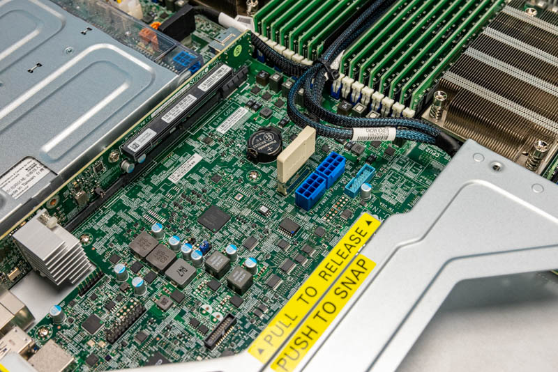
In terms of the risers, the primary riser has two PCIe Gen4 x16 slots. These are full-height slots. In a 1U server, having two slots means that the motherboard cannot extend beneath the riser so this is another case where that custom motherboard is helping the server design.
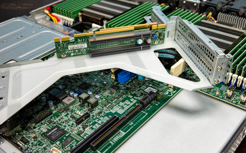
On the other side of the is riser, we get a low-profile PCIe Gen4 x16 slot. This “middle” low-profile PCIe slot has been in Supermicro Ultra servers for generations. What is different with this generation is that this is PCIe Gen4 and x16. In some previous generations, this was a PCIe Gen3 x8 slot and is often used for networking. We effectively get 4x the speed of those earlier iterations which means we can get, for example, up to 200Gbps of networking out of this slot.
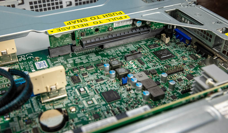
There is one additional riser though. Behind the Intel X710-at2 10Gbase-T NIC and heatsink, there is another riser slot. This is called an internal proprietary PCIe slot, but it is important to distinguish. Since this does not have access to rear I/O, Supermicro generally uses this slot for SAS RAID cards and HBAs. If you recall, those four 3.5″ front bays can be used as SAS3 bays. How that practically works is that a SAS card will be installed here, and some of the data cabling for the front panel will be switched to the SAS card in this slot.
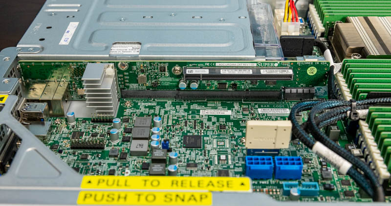
With that standard purpose, the slot can be used for more. Unlike some competitive systems, this slot is not a proprietary slot. In previous generations, we have used SSDs like Intel Optane SSDs in this slot since AIC SSDs do not near rear panel I/O access. That may not be an official configuration option, but it is available. Furthermore, this slot has moved from a PCIe Gen3 x8 slot to a Gen4 x16 slot as well which means much more bandwidth is available.
One feature that is not on the motherboard is M.2 storage. Supermicro’s basic design means that one needs to add M.2 storage via a PCIe riser, even if that is the internal riser. Looking at how densely packed this motherboard is, the logical impact of adding two M.2 slots would likely have been extending the motherboard and system. That would impact the ability of the server to fit in as many racks as it does in only 29″ of depth.
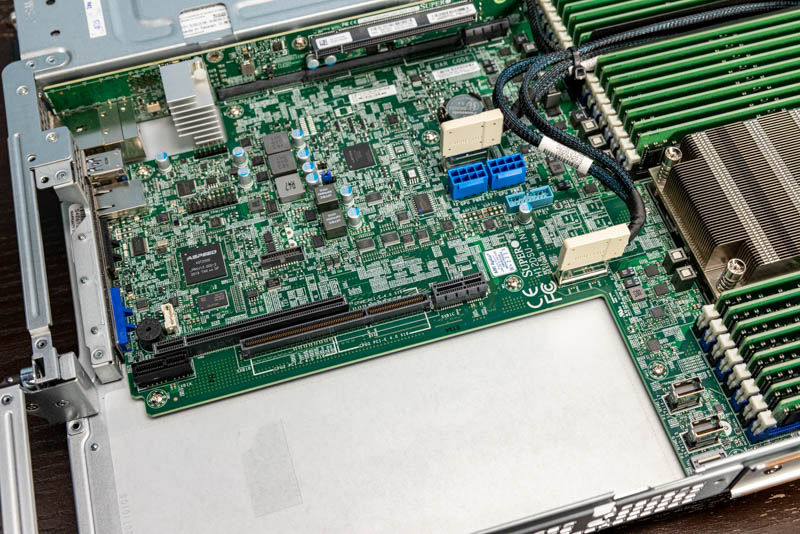
Hopefully, this hardware overview helps our readers understand both the what and why of the hardware design, but also a bit of how designs in one area impact other areas of a server design.
Next, we are going to get into the block diagram, management, performance, and our final words.

I wish STH could review every server. We use 2U servers but I learned so much here and now I know why it’s applicable to the 2U ultras and Intel servers.
Hi Patrick, does AMD have a QuickAssist counterpart in any of their SKUs? Is Intel still iterating it with Ice Lake Xeon?
I’m fascinated by these SATA DOMs. I only ever see them mentioned by you here on STH, but every time I look for them the offerings are so sparse that I wonder what’s going on. Since I never see them or hear about them, and Newegg offers only a single-digit number of products (with no recognition of SATA DOM in their search filters), I’m confused about their status. Are they going away? Why doesn’t anyone make them? All I see are Supermicro branded SATA DOMs, where a 32 GB costs $70 and a 64 GB costs $100. Their prices are strange in being so much higher per GB than I’m used to seeing for SSDs, especially for SATA.
@Jon Duarte I feel like the SATA DOM form factor has been superseded by the M.2 form factor. M.2 is much more widely supported, gives you a much wider variety of drive options, is the same low power if you use SATA (or is faster if you use PCIe), and it doesn’t take up much more space on the motherboard.
On another note, can someone explain to me why modern servers have the PCIe cable headers near the rear of the motherboard then run a long cable to the front drive bays instead of just having the header on the front edge of the motherboard and using short cables to reach the front drive bays? When I look at modern servers I see a mess of long PCIe cables stretching across the entire case and wonder why the designers didn’t try avoid that with a better motherboard layout.
Chris S: It’s easier to get good signal integrity through a cable than through PCB traces, which is more important with PCIe 4, so if you need a cable might as well connect it as close to the socket as possible. Also, lanes are easier to route to their side of the socket, so sometimes connecting the “wrong” lanes might mean having to add more layers to route across the socket.
@Joe Duarte the problem with the SATA DOMs is that they’re expensive, slow because they’re DRAM-less, and made by a single vendor for a single vendor.
Usually if you want to go the embedded storage route you can order a SM machine with a M2 riser card and 2x drives.
I personally just waste 2x 2.5” slots on boot drives because all the other options require downtime to swap.
@Patrick
Same here on the 2×2.5″ bays. Tried out the Dell BOSS cards a few years ago and downtime servicing is a non-starter for boot drives.
I should maybe add that Windows server and (enterprise) desktop can be set to verify any executable on load against checksums, which finds a use for full size SD cards for my shop (and greatly restricts choice of laptops). the caveat with this is that the write protection of a SD card slot depends on the driver and defaults to physical access equals game over. So we put our checksums on a Sony optical WORM cartridge accessible exclusively over a manually locked down vLAN.
(probably more admins should get familiar with the object level security of NT that lets you implement absolutely granular permissions such as a particular dll may only talk to services and services to endpoints inside defined group policies.the reason why few go so far is highly probably the extreme overhead involved with making any changes to such a system, but this seems like just the right amount of paranoia to me)