MiTAC Intel Denali Pass Air-Cooled Node
Here is the liquid-cooled node next to the air-cooled node. The air-cooled node has a hard airflow guide that spans the majority of the node, but it is extremely easy to get on and off using only two push tabs. Years ago, flimsy 2U 4-node airflow guides would get caught when plugging a node in, and that was annoying.
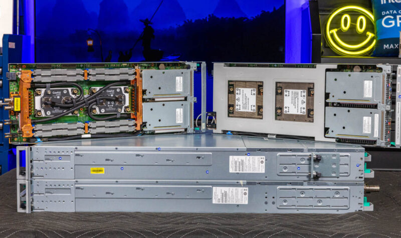
Hee is the same node with the airflow guide off.
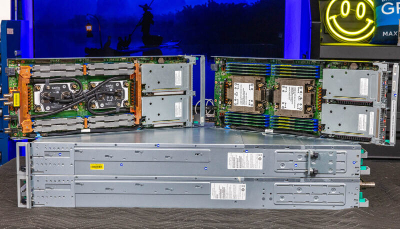
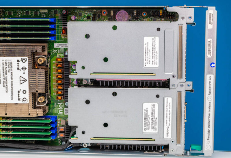
The node itself has the front I/O side, but more than half of the tray is made up of CPUs and memory.
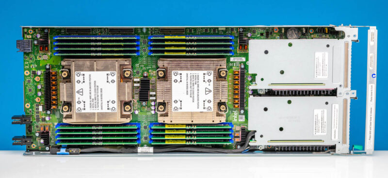
Here, we get two sockets for 4th and 5th Gen Intel Xeon CPUs up to 250W TDP. Each CPU socket gets a full set of eight DDR5 DIMM slots.
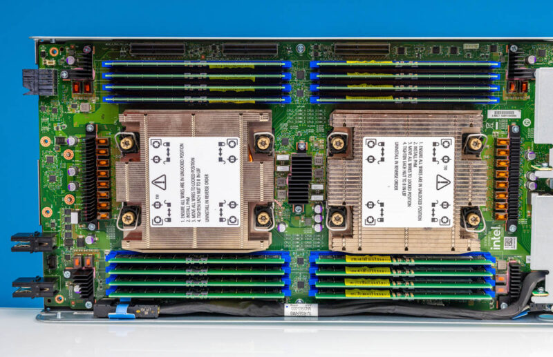
The node has two front PCIe Gen5 low profile risers, M.2 NVMe for boot, and basic motherboard components like the BMC, 10GbE NIC, and PCH.
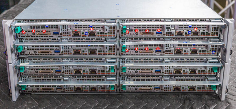
Something different about this system is that it uses a dongle for local KVM access. It also has a single 10Gbase-T port for OS management and a BMC port for the management processor. What it does not have is a storage array. The idea with this system is that it is more focused on HPC and uses high-speed networking to access large external stores of data.
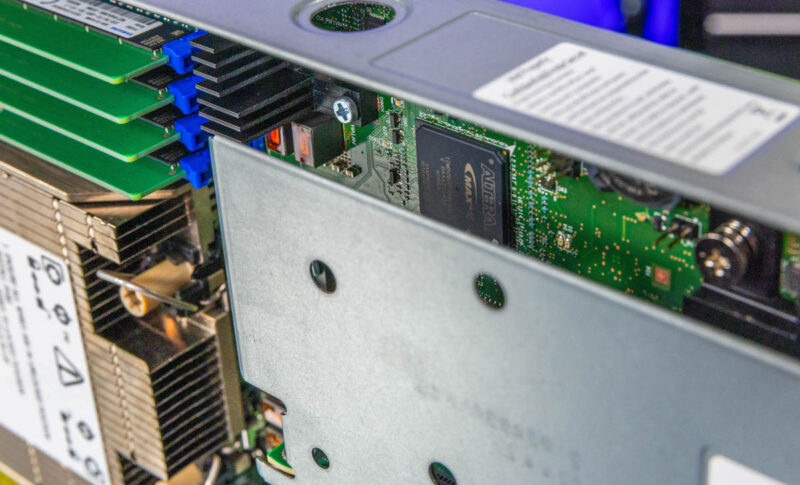
We even see a small Altera FPGA.
Next, let us get to the liquid-cooled version.
MiTAC Intel Denali Pass Liquid-Cooled Node
Let us get to it. What most folks will want to see is the liquid-cooled node, and here one is next to the air-cooled node.

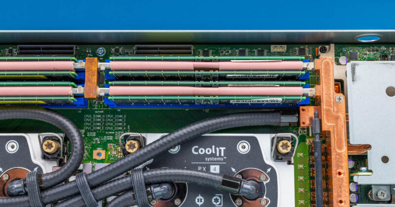
Just to level-set: This is not a simple “slap two liquid cooling blocks on” design. Instead, there are two cooling blocks for CPUs, two loops for motherboard components, and an entire perimeter for liquid distribution and memory cooling.
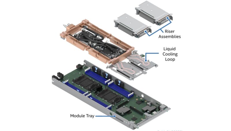
Here is what the CPU and memory area looks like in the liquid cooling node.
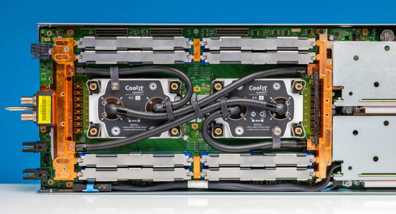
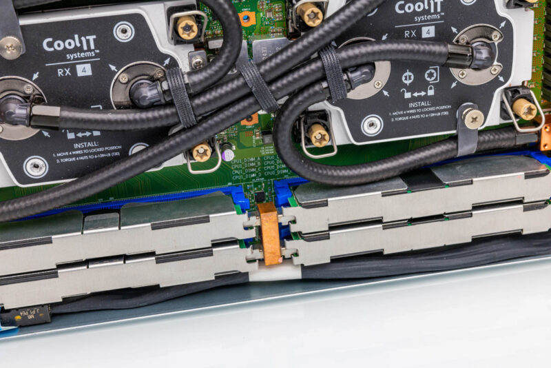
Around the memory modules, there are heat spreaders for the outside and then loops that run around the memory modules.
Taking those heat spreaders off, here is the liquid-cooled node.
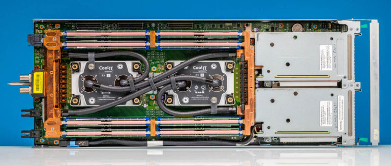
The DDR5 being liquid-cooled is a big capability since that is perhaps around 100W of components that would otherwise need to be air-cooled with fans.
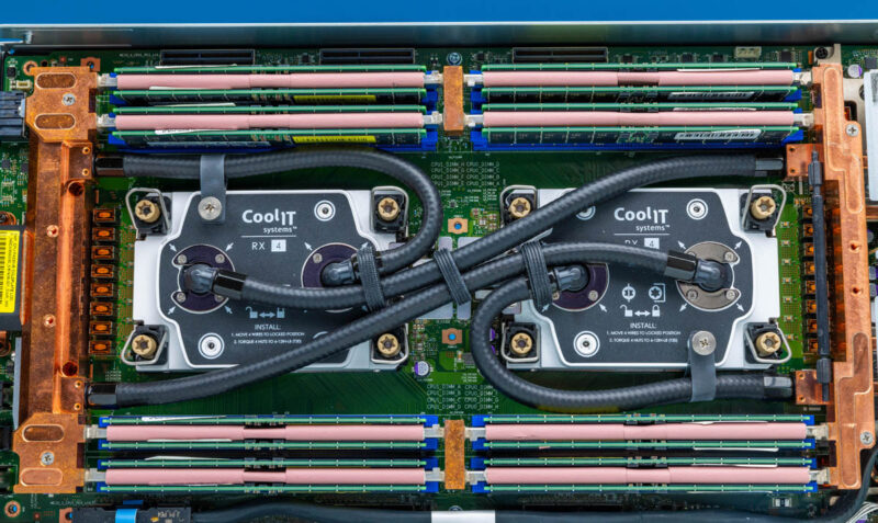
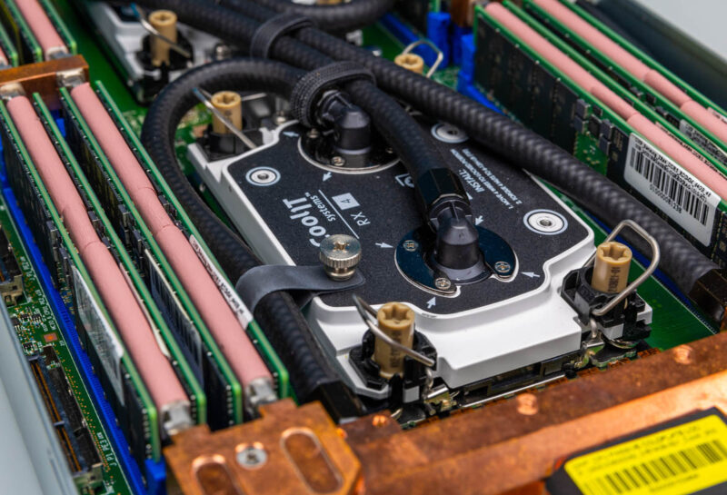
The main cold plates are from CoolIT.
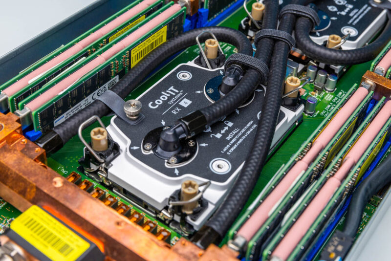
These are fed in parallel, instead of being fed in a series which helps keep temperatures down. If you want to learn more about CoolIT, you can see our How Liquid Cooling is Prototyped and Tested in the CoolIT Liquid Lab Tour.
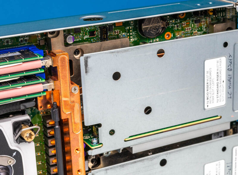
The liquid cooling loops also extend to the motherboard components. For example, we can see even the Altera FPGA is covered by the motherboard block under the riser.
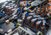
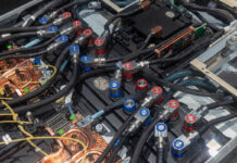
This is a photo just because we thought it looked cool.
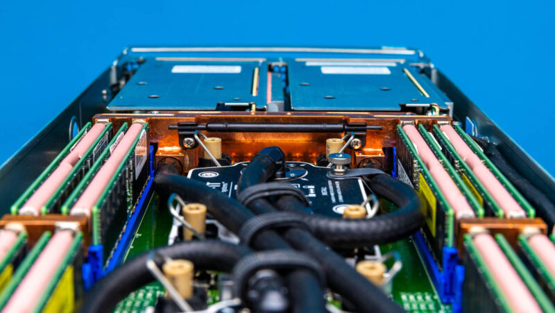
Of course, we get the same front I/O layout as the air-cooled node, we just get extra liquid cooling blocks inside. It is notable that the two low-profile PCIe Gen5 x16 expansion slots remain usable even in the liquid-cooled version.
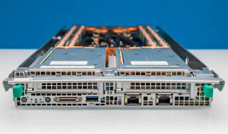
Since this is a parallel rather than a serial liquid cooling setup, we have more tubing. The tubes are sized to fit perfectly and then strapped together to ensure the node can still be easily serviced. After probably 60+ insertions and removals, we did not snag a liquid cooling tube.
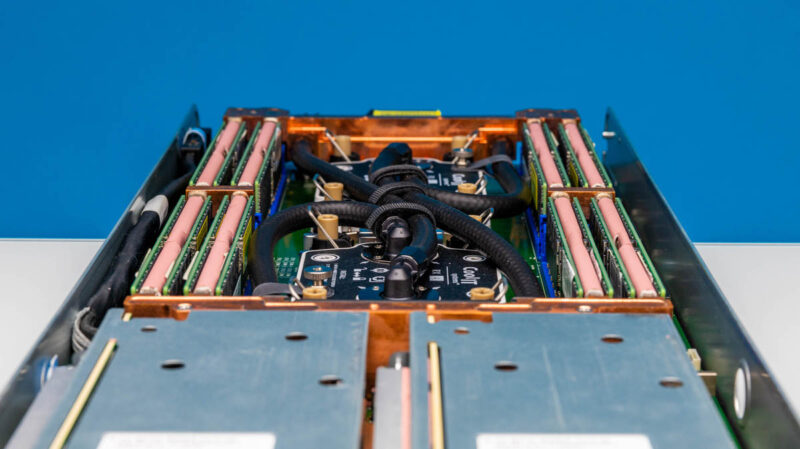
Of course, a lot of this is due to the distribution blocks found on the node.
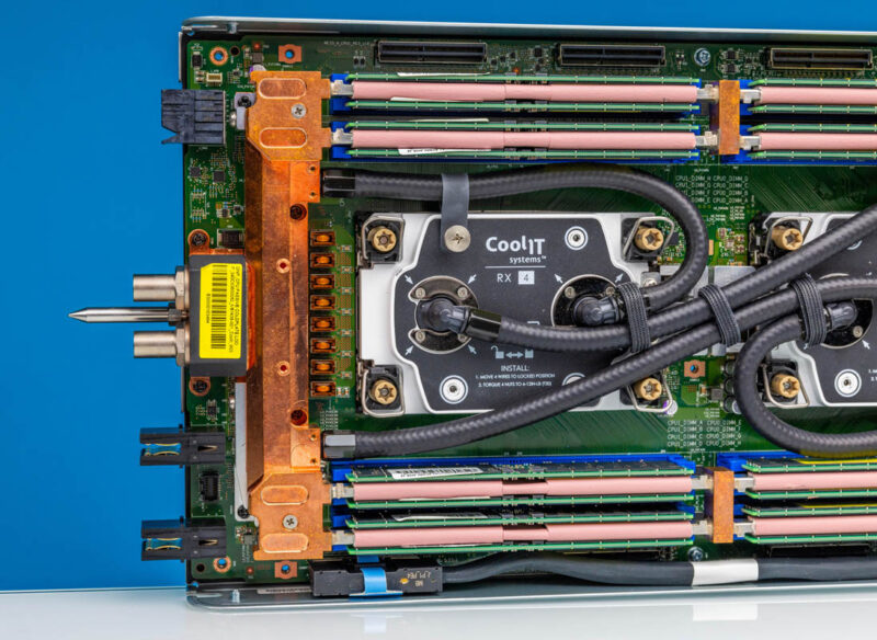
Since the coolant does not go through a PCIe slot, it needs to reach the rest of the loop somehow, and in this server it is on the edge with the power connections.
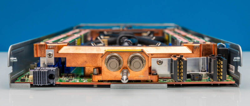
Each node has a guide pin and then the inlet and outlet quick disconnects.
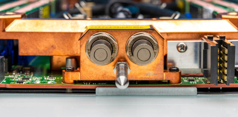
This is a huge change to the node since it means that everything is relatively precisely done compared to other systems. Different types and sizes of fittings need to connect cleanly.
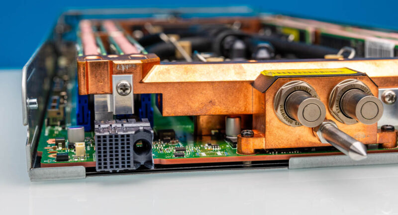
While this might seem trivial, it is a lot more work than systems that aim to cool less with liquid.
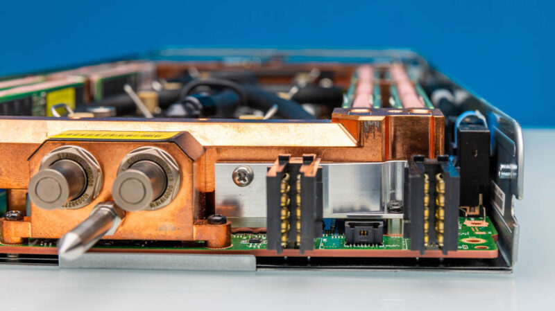
In case anyone was wondering, the connectors at the top of the motherboard are MCIO connectors. These are primarily for connecting to the expansion modules for GPUs and other accelerators when the system is configured for those.
Next, let us get to the block diagram.


It’s a work of art by former Intel guys. Unfortunately, no successors