MikroTik CRS520-4XS-16XQ-RM Internal Hardware Overview
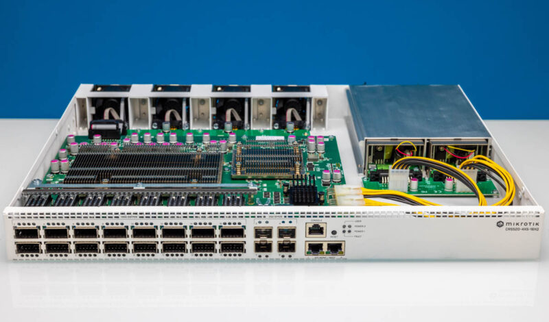
Here is a look at the switch open from the front.
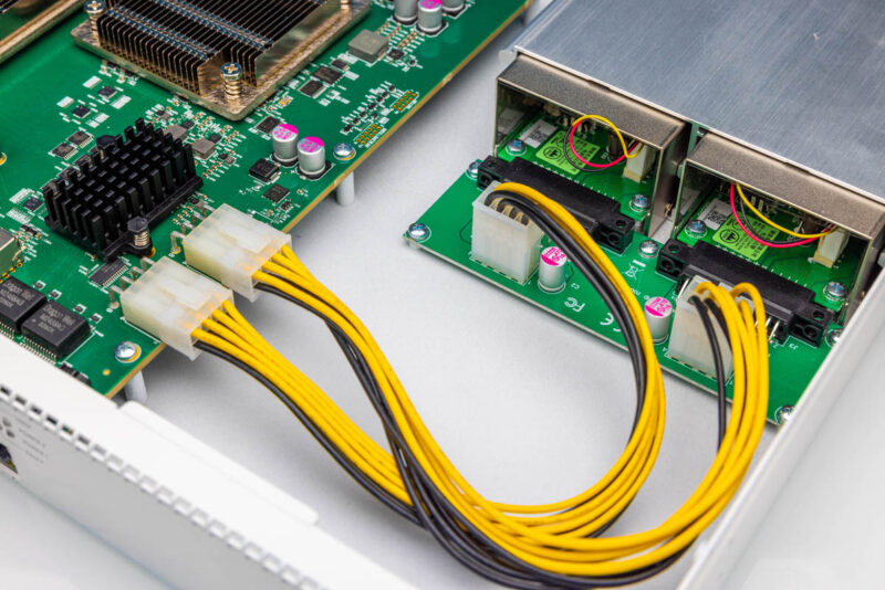
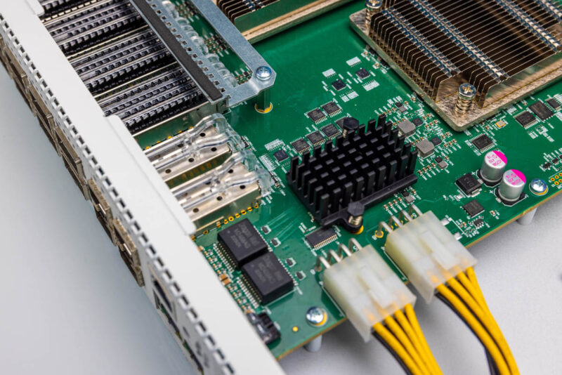
Since we just touched on the power supplies, let us touch on those first. MikroTik has a mating connector PCB for both power supplies and then wires take the power from that board to the main switch PCB.
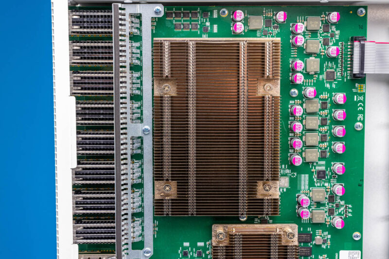
The main switch chip is the Marvell 98CX8410. There is not a ton on the 98CX8400 series but we managed to dig up a few details.
Next to the switch chip, we get a smaller heatsink for the management processor.
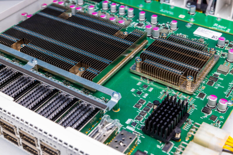
In this case, that is the Annapurna Labs AL32400 a quad core Arm processor from the chip company Amazon bought to make various Arm chips for AWS.
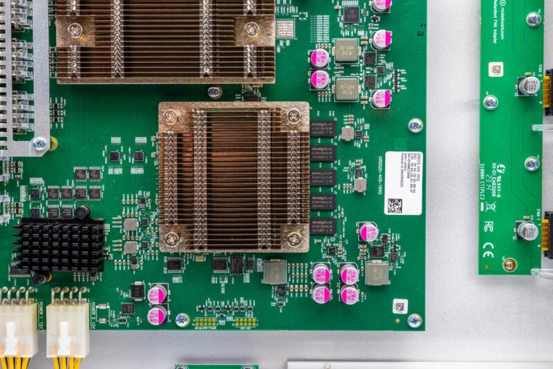
MikroTik uses the same CPU for some of its routers, so it is a quite high-performance option. While some MikroTik switches have 1GbE links to the management processor from the switch and management port, this is different. It has two 10Gbase-T management links alongside two 25GbE links to the switch chip. That means CPU-based features have a lot of bandwidth to the switch chip.
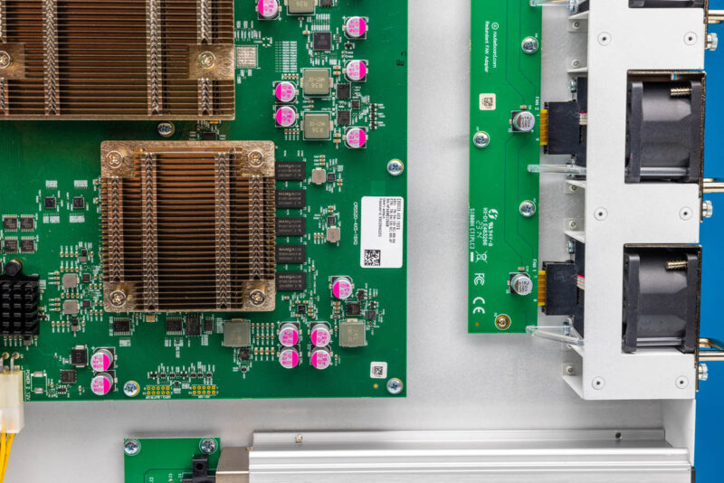
Since we have 10Gbase-T networking, we often need a PHY.
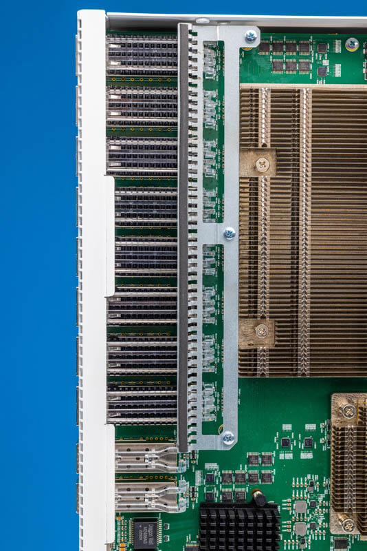
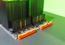
The switch PCB is in the middle of the QSFP28 ports, so there are eight on top and eight on bottom. MikroTik has this bar that goes across over the QSFP28 cage heatsinks. Our best guess on what this is for is to keep the plastic light guides in place for the port LED indicators. We think this is the case because we knocked off a SFP28 port’s LED light guide and those ports are not covered by this bar.
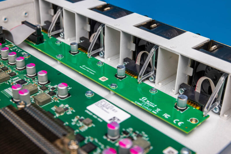
The main switch PCB is connected to a third board in the system via a ribbon cable. That third board is the fan board.
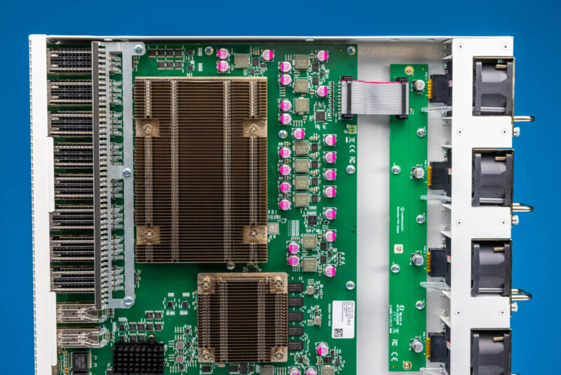
The fan board is where the hot-swap fan modules plug into.
Next, let us get into the switch.

If you want to use a full 100gbe you kinda need RDMA for windows. I have a 32 port 100gbe and most windows transfers max out around 40gb. Which is fine, I’m sure this switch works great as a 40g switch as well. I also hacked 120mm noctua high pressure fans into the top lid making it very much a TOR router by necessity. So something like this would be great.
However I didn’t go with iwarp compatible nics so there is a decent bit of switch compatibility required. Will they support PFC on the feature roadmap?
I wonder why so many switches go for the 1U full width form factor. You’d think if you went with 2U half width then you could get the same port density by putting two side by side, but you’d be able to use larger, more efficient fans and heatsinks, and quieter fans as well.
Hi, did you test the switch with high power transceivers?
Does it actually support modules with higher power classes. E.g. 80km 100G ZR4 modules will use 5.5W. Some devices will refuse to operate transceivers with a higher consumption than 3.5W.
Given the low power budget left for transceivers it seems like it’s designed for use with only twin ax DAC cables. Even 16 x low power 2.5 watt SR4 transceivers would be a problem. Is there any official word from mikrotik regarding transceiver power budget?
RouterOS 7.15 seemed to have added some initial support for PFC, and 7.16 seems to be refining a bit more.
Here’s the thread on QoS:
https://forum.mikrotik.com/viewtopic.php?p=1089316#p1089316
You can see I asked about clarification on RoCE towards the bottom but haven’t received an authoritative response – only a community member stating “You don’t need DCB support, just use RoCE v2” which I don’t consider to be a great answer. Maybe if yall want to ask as well and help me bring focus?
I’m sure Patrick / STH is also asking Mikrotik, as it came up in previous videos with the 4 port 100Gb CRS 5xx switch.