
After last week’s Going 800Gbps at up to 1000km with the Marvell COLORZ 800 piece, some folks may have seen that we also took apart a 100G QSFP28 DAC and a 100G SR4 QSFP28 optical module. We thought it would be worth showing folks what is inside the modules so this article is going to show what is inside the DAC’s housing.
Inside a QSFP28 DAC Housing
The cable we are going to open is one marked as an Intel DAC. This is a fairly typical QSFP28 DAC that has the electrical connector on one side and then a cable to the other side.
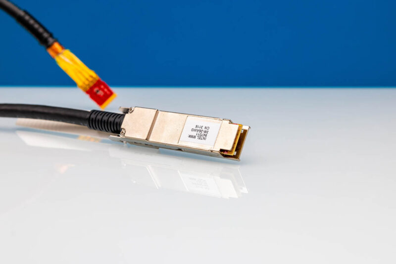
Taking apart the casing was easy. Some, like this one, use simple screws to hold them together. Some others use harder to take apart attachment methods. We would suggest if you do this yourself that you try it on one that has easy to access screws. Also, be aware that there is often a spring for the QSFP28 retention mechanism. Those have been known to spring for freedom off a workbench when opening these up.
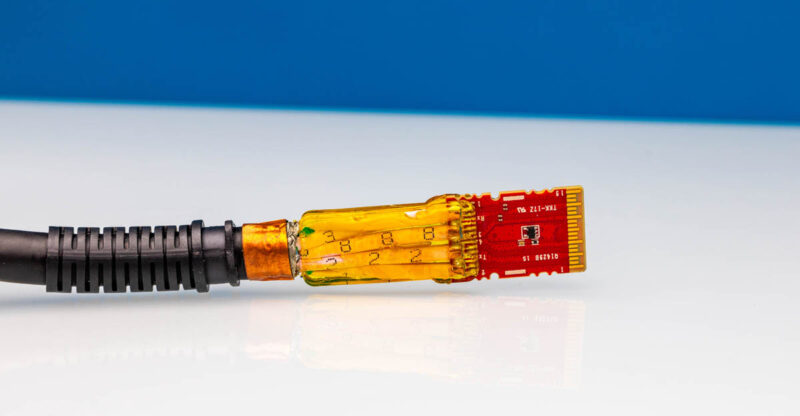
Inside the casing, we can see that the PCB is very simple. Indeed, you can actually see many of the traces between the QSFP28 connector and the wires that go inside the cable.
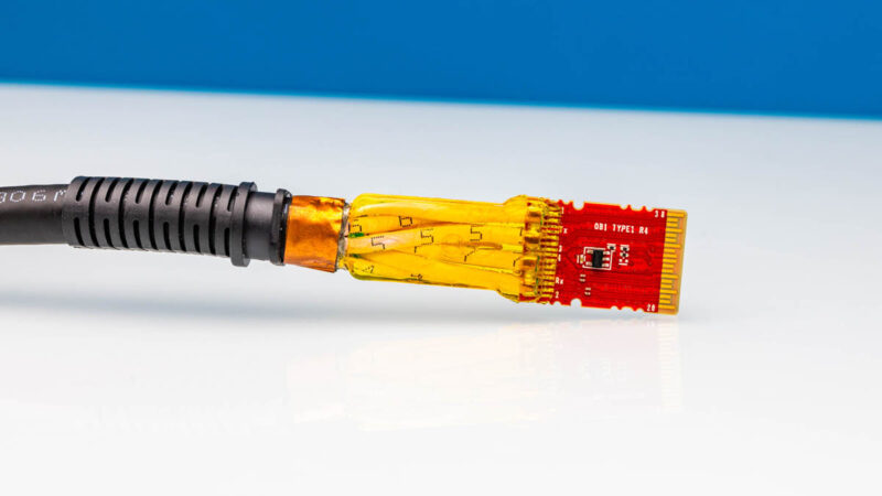
This module has thick wires with shielding that go the length of the DAC. Each wire is given a number that presumably helps in manufacturing. The connections and the start of the wires are then encased in some sort of resin or epoxy to ensure that they do not break off of the solder points on the PCB. Then we get some copper tape and a flexible exit to the cable with some bend support. Both sides look very similar.
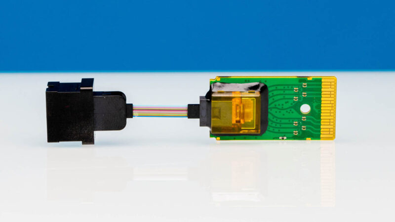
Just for some reference, here is the assembly inside a low-cost QSFP28 100G SR4 optic, and only the PIC side. The alignment of the optical fibers has to be more exact and the photonic to electrical circuits are significantly more complex than inside a DAC.
Final Words
Looking inside a DAC is not something most folks will ever need to do. These are designed to be plug and play without any maintenance. At the same time, we figured we would take the casing off of one end just so folks can see how these work. We should at least point out that these are passive cables. There are AECs or active electrical cables that have active retiming chips in the cable’s connectors that help signal quality and high-speed signals go further over copper. Those AECs are a bit more complex, use more power, and cost more. Still, when we talk about how relatively simple a DAC design is, hopefully these photos should help give you some sense.


Really cool, thanks for sharing. I always like a good teardown. :-)