This is going to be one of the most fun reviews we have done. Specifically, we are going to see how liquid cooling works as part of this Gigabyte H262-ZL0 review. The Gigabyte H262-ZL0 is a liquid-cooled 2U 4-node AMD EPYC server. As a result, we had a little challenge. Our liquid cooling lab is not quite ready, so we are leveraging CoolIT Systems’ lab for this, since they make the PCLs or passive coldplate loops in the Gigabyte server. We recently went up to Calgary in Alberta Canada and I built an entire liquid cooling solution from assembling the Gigabyte server to connecting everything. I brought twelve 64-core AMD EPYC Milan CPUs, 64x 64GB DDR4-3200 DIMMs, several Kioxia NVMe SSDs, and more up to Canada so that we could test out a reasonably high-end configuration.
The net result is that we have a solution built on a test bench that was capable of cooling over 20,000 AMD EPYC 7003 “Milan” cores using the flow from a garden hose of water. This is more than your typical STH server review as this is going to be really cool (pun not intended, but welcomed.)
Gigabyte H262-ZL0 Hardware Overview
This review is going to be a bit different. We are going to start with the chassis, but then we are going to get to the liquid-cooled nodes as well as the entire liquid cooling loop. Before we get too far in this, let me just say this is one of the pieces that I think genuinely may be better in a video than it is in its written form. We have that video here:
As always, we suggest opening this is in its own YouTube browser, tab, or app for the best viewing experience.
Gigabyte H262-ZL0 Chassis Overview
The Gigabyte H262-ZL0 is the company’s 2U 4-node server. Each node houses two AMD EPYC CPUs. When we are discussing this server, the -ZL0 means that the server is liquid-cooled with the CPUs only being cooled by the liquid loops. There is a -ZL1 variant that adds cooling for the RAM as well as the NVIDIA ConnectX fabric adapters. We decided not to do that version just because I already had >$100,000 of gear in my bags and we needed to de-risk the installation to a single day with filming. For longtime STH readers, we have reviewed a number of 2U4N Gigabyte air-cooled units, but this is the first liquid-cooled Gigabyte server we have reviewed.
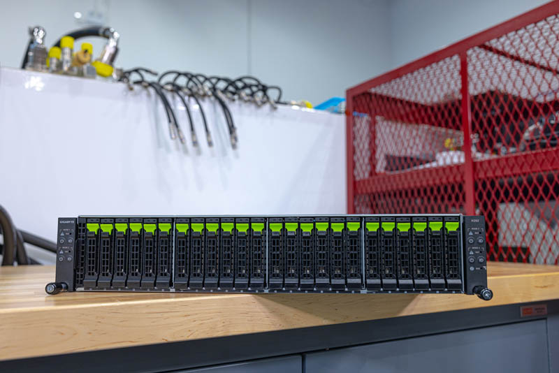
The twenty-four drive bays are NVMe capable. Each of the four nodes gets access to six 2.5″ drive bays. We will note these are SATA capable as well, but with the current SATA v. NVMe pricing being similar, we do not see many users opting for lower performance SATA instead.
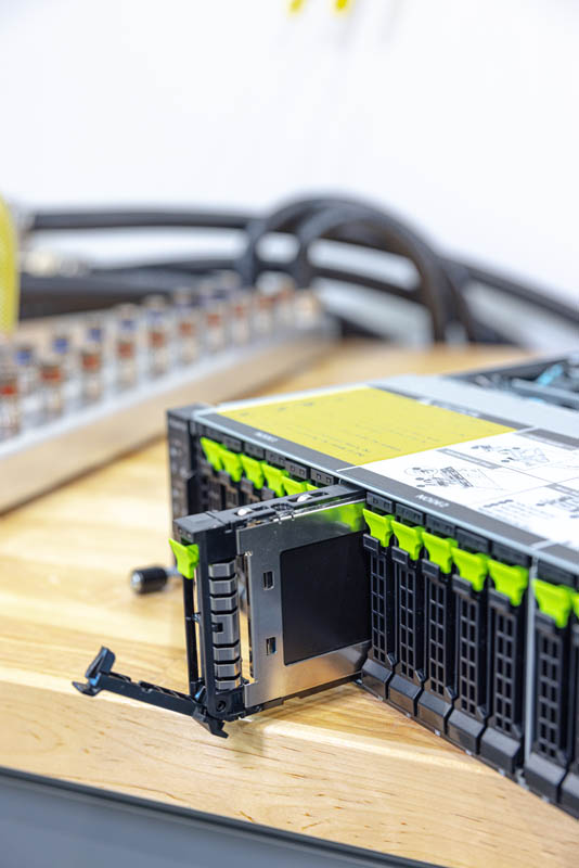
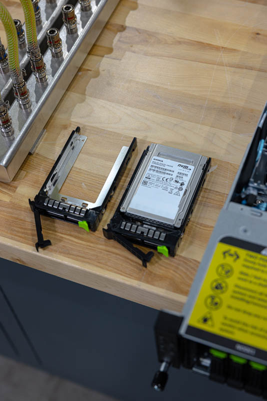
One nice feature is that these drive trays are tool-less. It took Steve longer to snap these photos than it did to install all of the drives.
Gigabyte has a fairly deep chassis at 840mm or just over 33 inches. One can see that Gigabyte also has a service guide printed on the top of the chassis. We are going to work our way back in this review.
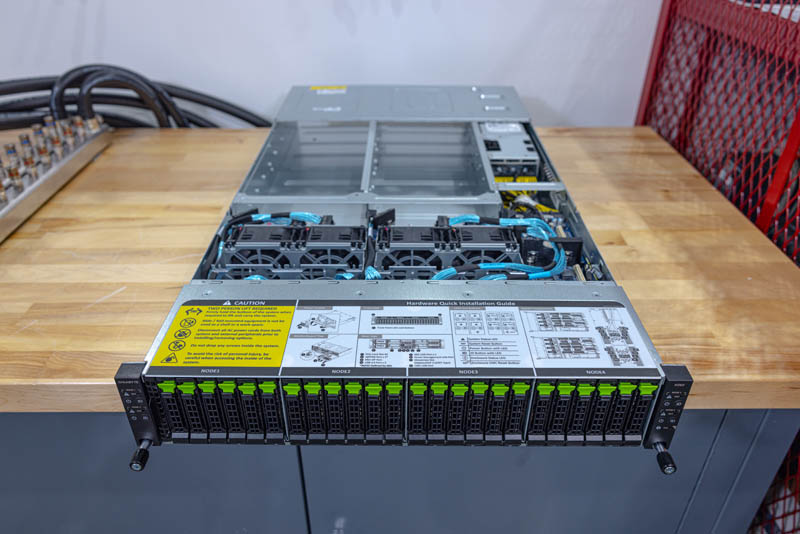
The system still has a middle partition between the storage and the nodes/ power supplies that is for cooling and the chassis management controller. The chassis management controller helps tie together all four systems from a monitoring and management perspective via a single rear network port.
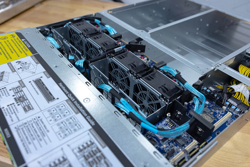
The fans are interesting. We only have four fans, but spaces for eight. With liquid cooling, we are removing ~2kW of heat from the chassis without the fans, so there is a lot less need for fan cooling. In the video, we have a microphone next to these fans in an open running system with all four nodes going and they are still relatively quiet.
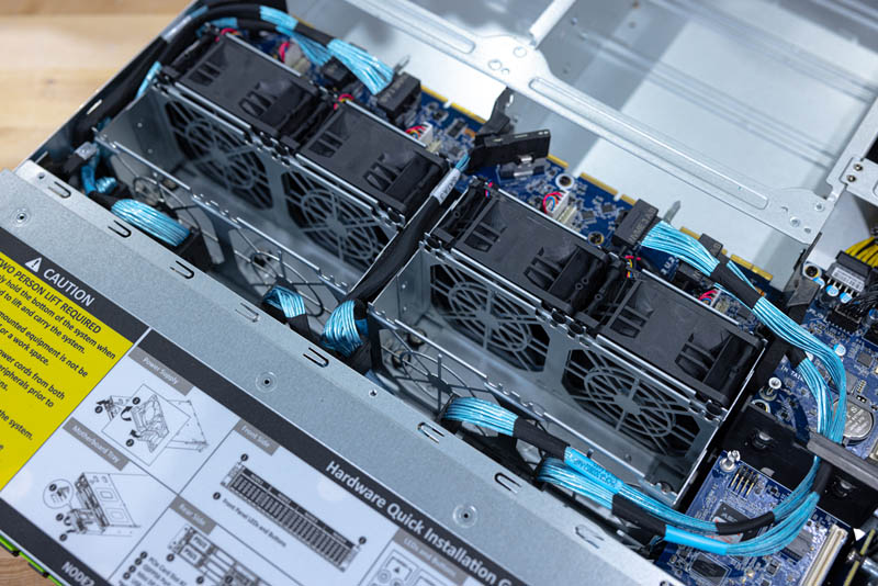
Here is a look at how the nodes plug into the chassis from the rear side of the chassis.
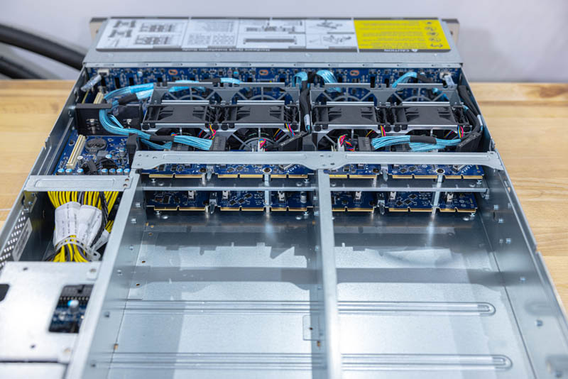
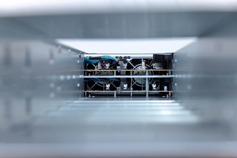
For another perspective, here is a view looking through the node tunnels to the connectors and fans. Each tunnel houses two dual-socket nodes. The nodes simply slide into the tunnel and can be easily removed for service.
The power supplies are 2.2kW 80Plus Platinum units. The reason we can use these PSUs with a dense system like this is that we have the lower system power due to the heat being removed via the liquid cooling loops.
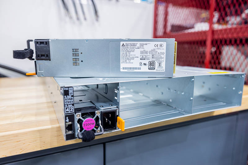
One can also see the CMC network port next to the bottom PSU and a quick node map so it is easy to tell which node is which.
Next, let us get to the big show and take a look at the liquid-cooled nodes in the server.



Per the server cooling concepts shown in this article, my 2012-2021 gig as Sys Admin / Data Center Tech with the last few years immersion cooling infused, upon testing a system like the one shown here myself, I felt I was drifting towards being a Sys Admin / Data Center Tech / Server Plumber.
…Seeing my circa 2009 air-cooled racks with less and less servers-per-rack over time, and STH’s constant theme of rapidly increasing server CPU TDPs, data center techs need to get used to a future that includes multiple forms of liquid cooling.
This begs only one question: How much energy and water use for data centers (and coming soon/arrived to home users with the next gen nvidia gpus and current course of cpus) will break the camel’s back?
While it’s great that everything has become more efficient, it has never lead to a single decrease in consumption. A time during which energy should be high on everyone’s mind for a myriad of reasons and the tech hardware giants just keep running things hotter and hotter. I’m sure it will all be fine.
Amazing article. I’m loving the articles that I can just show my bosses and say ‘see…’
Keep em coming STH
P2 has really nice photos of the pieces. I’m liking that.
Very informative. The flow of useful informations was steady and of a high quality.
Awesome!
Patrick, next time you get your hands on something like this, could you try and see if you could open one of the PCL’s coolers. As a PC watercooling enthousiast, I’m curious to see whether the same CPU cooler principes apply. Particularly considering things like flow rate and the huge surface area of EPYC CPU’s.
Furthermore, it might be funny to compare my 4U half-ish depth water to air “CDU” with flow rate and temperature sensors with the unit you demonstrated in this review. Oh, my “CDU” also contains things like a CPU, GPU, ATX motherboard ;-)
How much power would the chillers consume though? This is definitely a more efficient way to transfer the heat energy somewhere else. I’m not so sure about the power savings though.
Bill, it depends, but I think I just did back of the envelope on if you did not even re-chill the water and just passed water through adding heat. It was still less than half the cost of using fans. Even if you use fans, you then have to remove the heat from the data center and in most places that means using a facility chiller anyway.
Would have been interesting to know how warm the liquid is going in and out. Could it be used to heat an adjacent office or residential building before going to the chiller?
With high-density dual-socket 2U4N modules, for example, there seems to be one socket which gets the cooled first and the exhaust of that cooling used to cool the second.
If I understood the plumbing correctly the water which cools the first socket in the setup tested here is then used to cool the second socket. RAM is air cooled but again the air is passed over the first group of DIMMs before cooling the second.
Under load I’d expect there to be a difference in the temperature of the first compared to the second. In my opinion measuring this difference (after correcting for any variations in the chips and sensors) would be an meaningful way to compare the efficiency of the present water cooling to other cooling designs in similar form factors.
How about the memory cooling, storage, and network? You still need the fans for that in this system.
With DDR5 memory coming up and higher power there will be a much smaller savings from a cpu only liquid cooled system.
Any chance to publish the system temperatures too?
Thanks!
Mark, mentioned this a bit, but there is another version (H262-ZL1) that also cools the memory and the NVIDIA-Mellanox adapter, we just kept it easy and did the -ZL0 version that is CPU only. I did not want to have to bring another $5K of gear through customs.
Very insightful and informative article.
I just finished re-building my homelab based on a water-cooled Cray CS400-LC rack and the power of water cooling is just amazing.
Certainly on this scale a very interesting topic from an engineering standpoint.
The commentary here is equally as good as the article. Depending on the physical location, the building envelope, and sensible load generated by the equipment, would be interesting to see a energy simulation/financial model of various design concepts for 1) the typical air cooled design 2) PCL shown above 3) immersion cooling w/ chillers or 4) (my personal favorite design concept) immersion cooling with a cluster of large oil reservoirs as thermal batteries. The cooling loop is switched between reservoirs for the heat transfer schedule. No fans. No chillers. Just 2 pumps and a solenoid manifold bank. This would work great in areas such as Northern Canada.