Inside Marvell’s Optical Lab with the COLORZ 800 ZR+ Optical Module
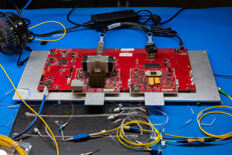
It turns out that placement of components within an optical module is a big deal. Placement of one component a millimeter different can have a big impact on its operation. Usually, with these high-end modules, companies do not like us taking them apart. Instead, we got to see the lab demo at Marvell that is like a big version of what goes in that small metal OSFP housing.

Of course, a big board laid out like this is not practical to put into networked devices, so the other part of what makes this so cool is not just being able to make a 400Gbps 2500km or 800Gbps 1000km communication module, but it is also being able to package it into a standard pluggable form factor module.
Taking a look at the platform, the first thing you will notice is the short DAC. This is the 800Gbps electrical signal side.
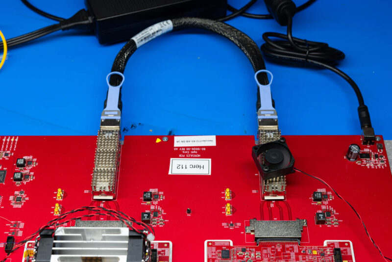
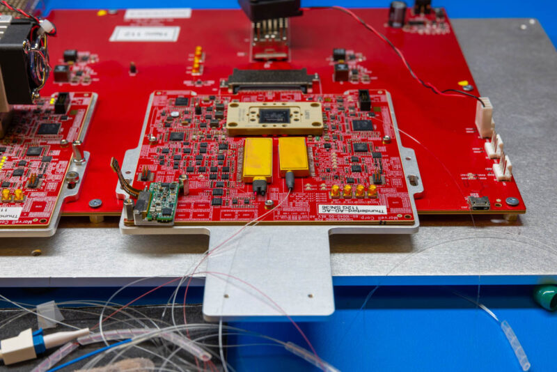
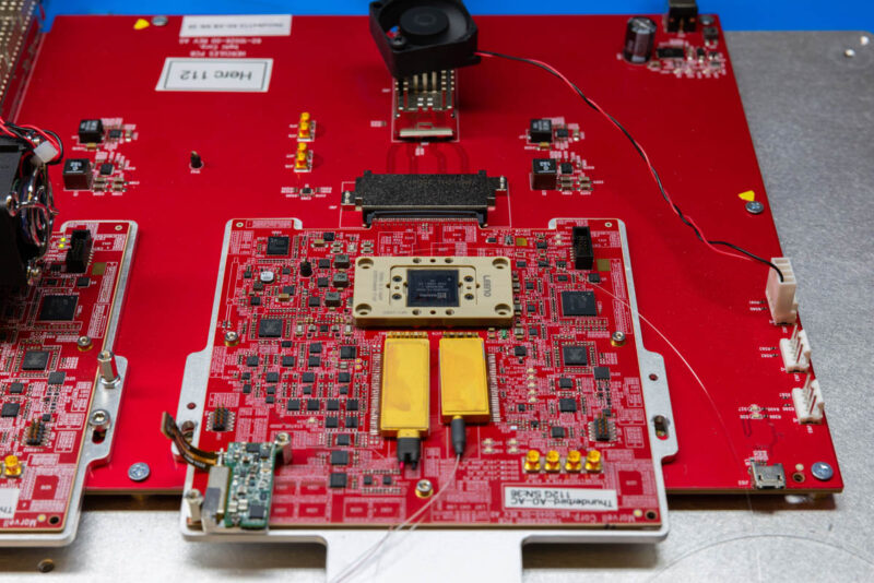
Here is a view of the development board from the other side.
You can imagine this as the the electrical side of the module that you can see here:
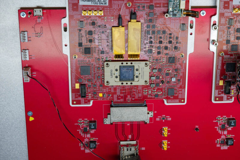
The first stop is going through a Marvell Orion DSP. That is the component between the electrical side and the optical side that is there to clean up the signal.
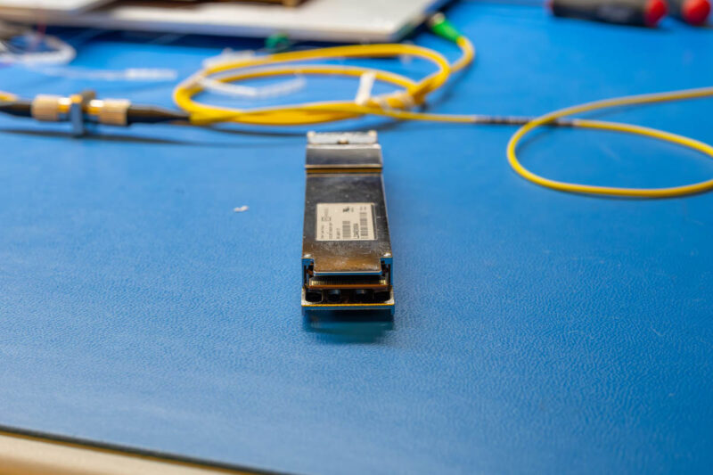
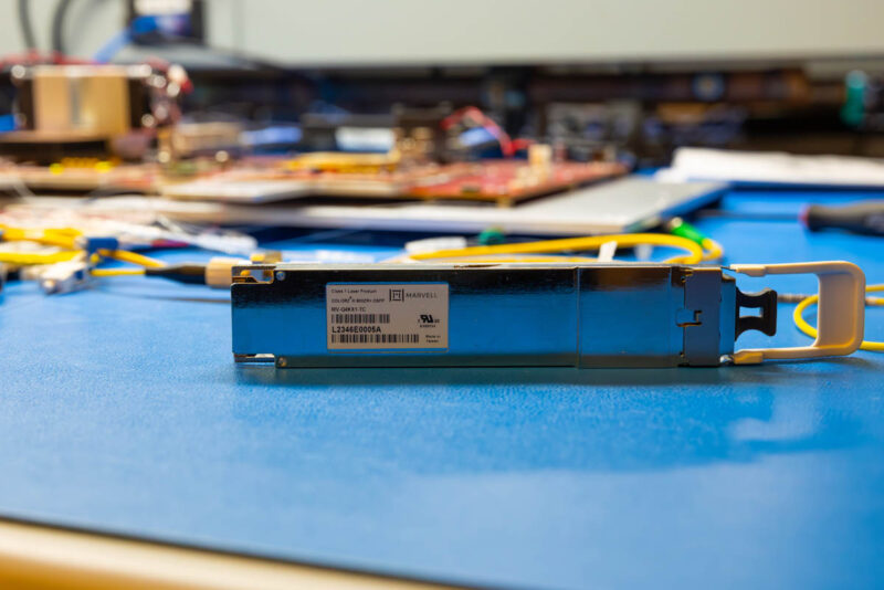
To give you some sense, here is the Marvell Orion DSP next to the COLORZ III 800G ZR+ module that it goes in. That OSFP module is above the older generation COLORZ II (400G) and COLORZ I (100G) pluggables.
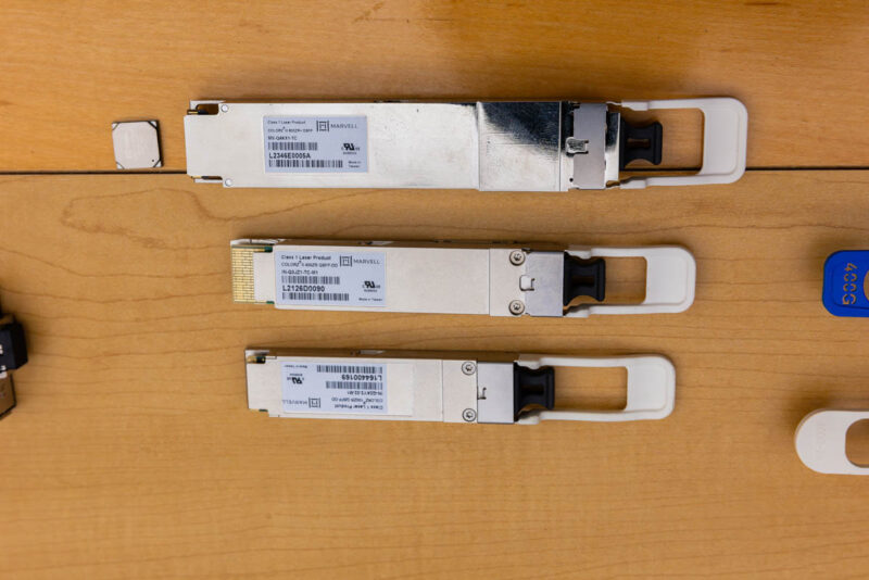
These DSPs are neat because they need to do a lot in very space and power constrained environments. While your average 10Gbps or 25Gbps NIC chips are manufactured on significantly older generation process technology, these DSPs were built on 5nm process to enable the processing in the power and space constraints of the OSFP module footprint.
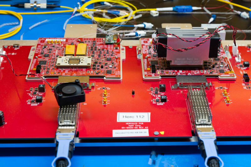
From the DSP, the send signal then goes to the CDM, or Coherent Driver Module which is the smaller of the two gold/ brass colored boxes below with the single fiber connected.
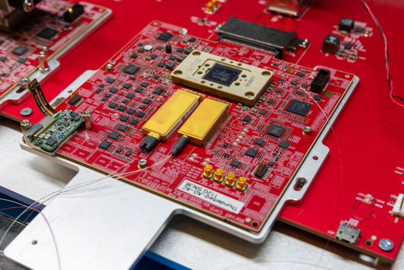
We are not going to go deep into how PICs work, as an example, but in that little box we have the components needed to convert the electrical signal to an optical signal using a laser light source, modulators, and other components. On one end of that box we input the electrical signal and on the other end we are outputting light onto a fiber optic strand. That is the transmit side of what is on this demo board.
You will probably guess at this point that the left hand, and slightly larger, box is the receive side called the ICR, or integrated coherent receiver. Immediately something should jump out, especially if you have used singlemode LC cables and optics regularly: there are two fiber cables going into the receive side. That is where this technology gets a bit more complex than lower-cost and lower-speed optics that are just doing direct detection (“is there light or is there not light” type of analysis.)
Instead of simply having a single receive side fiber, there is a local osciallator on the board that feeds a second signal into the ICR. Think of that as a reference signal. Inside that ICR is a 90 degree hybrid, a passive component that helps maintain things like the phase and magnitude information. That ICR also houses the photodetector that receives the optical signal before producing an electrical output on the other end. That electrical signal is usually weak, so we have a TIA or a transimpedance amplifier that takes that weak electrical current from the photodetector and adds voltage that can be measured. Think of that as an amplifier for the electrical side.
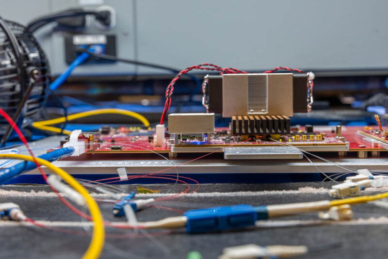
Normally, these components also need cooling, so the reference board looks more like this:
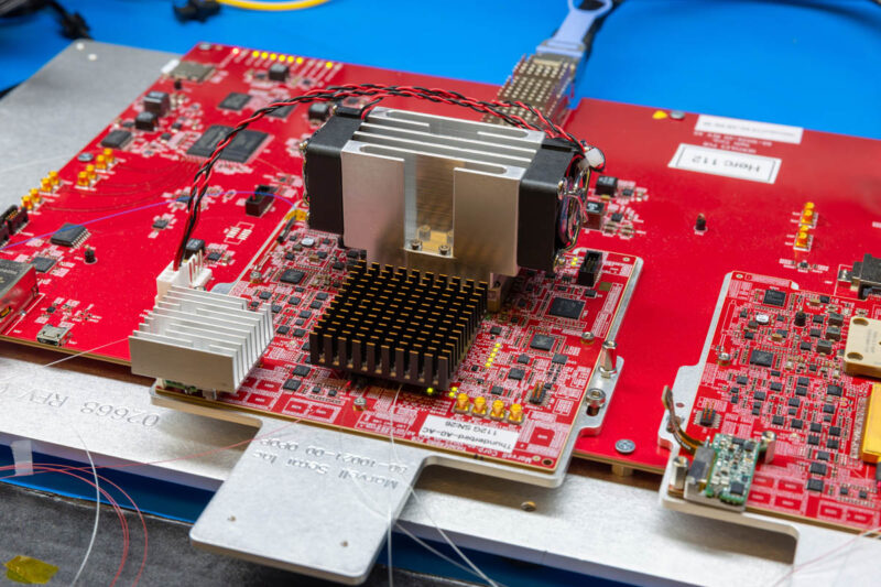
Even the reference laser source needs a heatsink. You can also see when I say that we managed to get access into a lab, this was truly a lab environment.
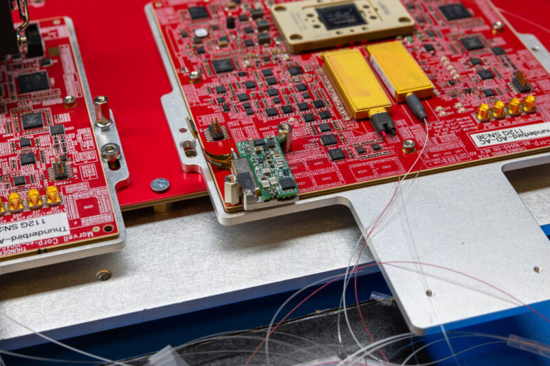
That electrical signal from the ICR can then be fed into the Orion DSP on the electrical side.
That brings us full circle with a loop on the electrical side and the optical side.
Not to be understated here, but each side of this development platform ends up being packaged, and cooled, within the OSFP form factor.
Beyond the hardware, I wanted to take a quick look at why we need that reference laser signal and the difference between direct and coherent detection.


The only things that lab table is missing are:
– DUCT tape
– SuperGlue
– Coffee cup
What a superior Friday read. I could’ve handled more depth, but I’ve been doing this many years.
It’s good to have a Kennedy back in optical networking. You look like I remember your dad when I first met him when I was the buck with a newly minted PhD 20 years ago.
I always wondered if you’d go here.
Cool demo but I feel that this type of hardware is on the way out in favor of chips that leverage silicon photonics. The advantages are way too great to ignore in terms of power and potential bandwidth. Simpler encoding schemes tend to win in the end and this is a straight forward means to maintain simplicity without the need for highly complex DSPs in the transceivers (complex here is relative).
That convergence diagram looks like QAM 16 encoding, at least visually. Hardware exists to do QAM 4096 (see Wi-fi 7) but at a significantly lower real clock speed. I don’t think that there is enough sensitivity to go that high in modulation but QAM 16 does appear to be low resolution for what it is capable of. Perhaps with 1000 km of cable in between modules, the images are not so clean.
The ideas of expanding out a traditional data center using these modules is feasible but a pair of links for a big GPU cluster isn’t going to cut it: each GPU node nowadays is getting 100 Gbit of networking bandwidth and 800 Gbit would only be a means of linking up two big coherent frames of gear. An order of magnitude more bandwidth would be necessary to really start attempting this. If a company is willing put down tens of millions of dollars for a remote DC, then spending a few million to lease/run more additional fiber between the locations is a straight forward means by using more cables. Optics is fun in that signals can be transformed in transition to an extend (polarization filters as an example) to merge multiple lines together on to a single cable without interference. That is a way to aggregate more bandwidth over existing lines but what ever is multiplexed on one end had to be demux on the other side. This is also ignoring that such aggregation technics are not all ready used inside of the module (and my simple polarization example likely wouldn’t work with those described in this article). These techniques also incur some signal loss which directly impacts their range.
This tech is at its own level, and I could see it being a big deal for long-distance (subsea?) cables where it might be worth investing a lot in gear at each end if it lets you avoid repeaters/retimers along the way. Would welcome the explainers on optics!
It’s also *wild* how far commodity fiber stuff has come. This is a bit of a market fluke, but a ton of used Intel 100G 500m transceivers are out there that you can pick up on eBay for $10. New optics still wouldn’t be much of the cost of a 100G deployment. Even higher-end stuff doesn’t look ridiculous proportionate to what it’s doing, and isn’t single-vendor unobtanium.
DWDM is also incredibly cool! If you’re a giant multi-datacenter operator, maybe it’s simpler to just get 800G everything and be done with it, but conceptually it’s really neat that you can lay a many-strand cable and gradually get to 400G or 1T/strand, one 10 or 25G wavelength at a time.
It was only pretty recently I picked up even a vague awareness of what modern networking is able to do, since work hasn’t dealt in physical hardware for a while. Keep the posts on fun network stuff coming!
I don’t understand the mentions to AI, if you visit the OpenZR+ website it is very clear that the target market of these products are big telecom providers and their transport networks.
Thanks Patrick! Great stuff as always.
One question I’m asking my pluggable optics vendors these days is:
Will your 800G coherent modules work in my 400G router?
Specifically, I’m *really* interested in the extra-long reach capabilities of the 112GBaud QPSK 400GE encoding 800ZR+ opens up, & with the host side running at 56GHz per lane it might just fit within the existing 25W QSFP-DD power envelope. Also the L-Band possibilities are quite interesting.
Even if those particular modes aren’t supported, the economics have changed. If you install more than a handful of these optics in your router, you probably spent more on your optics than your router, & they likely consume more power & put out more heat than the router itself…