Dell S5148F-ON Internal Hardware Overview
Inside the switch, we have a fairly standard layout with ports, the switch chip and its PCB, and then the management and power/ cooling.
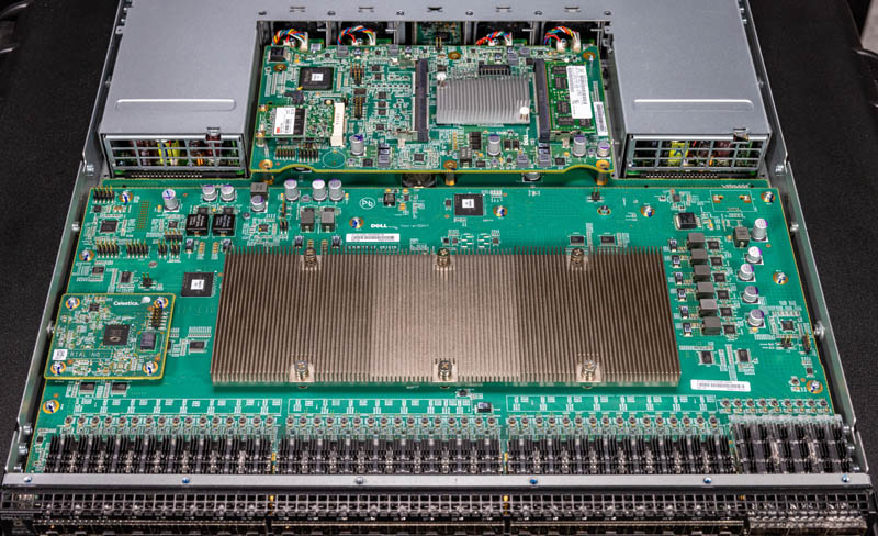
Here, the switch chip is a Cavium XPliant (now Marvell) part. This switch chip sits below this large heatsink.
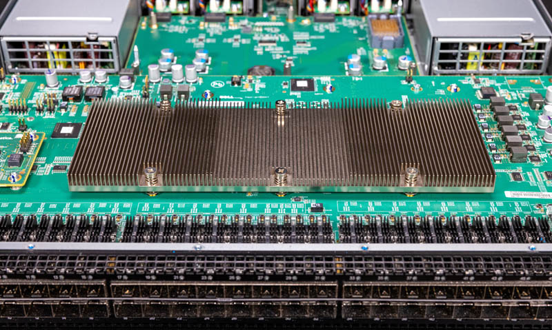
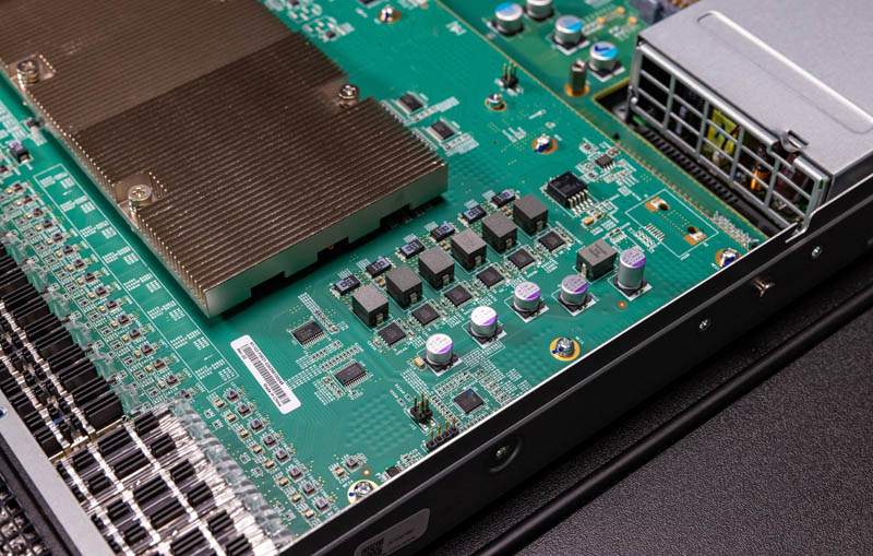
Here is a look from the other angle. Something to note here is that the airflow management is nowhere near what we are seeing on higher-end 32x400GbE switches these days. For some sense of scale, those higher-end 1U switches put all of the port bandwidth of this switch onto just 4.5 ports, so as one can imagine the newer generations are also using more power.
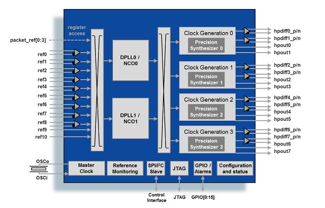
Something that is a bit different on this switch is this Celestica board. This appears to be a Celestica OEM switch with Dell customization but we cannot confirm beyond this board other than by looks. This board houses a Microsemi ZL30363 (now Microchip) chip.
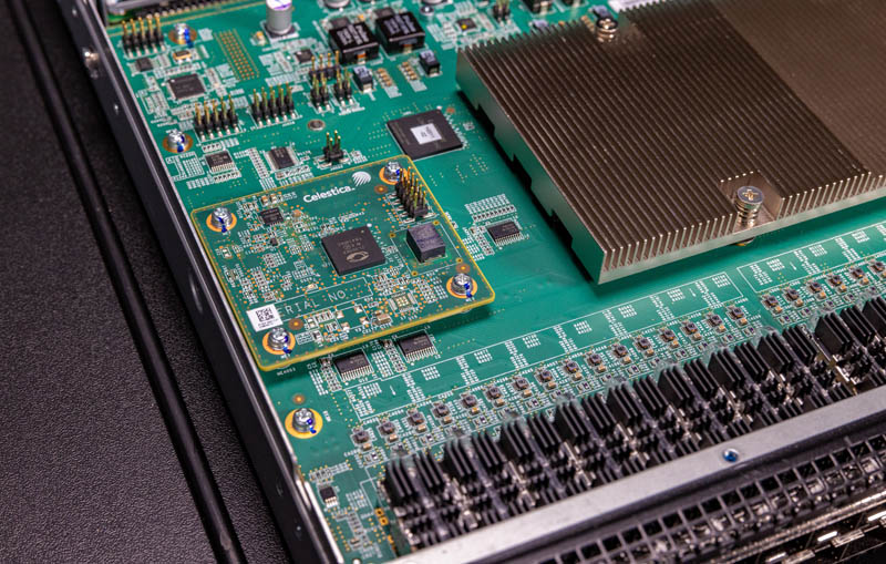
This is an IEEE 1588 and synchronous ethernet packet clock and dual-channel network synchronizer. Feel free to look it up a bit more, but here is the block diagram for that.
The other side is actually relatively clean. Often on switches, we see a number of FPGAs on both sides of the switch PCB but that is not the case here.
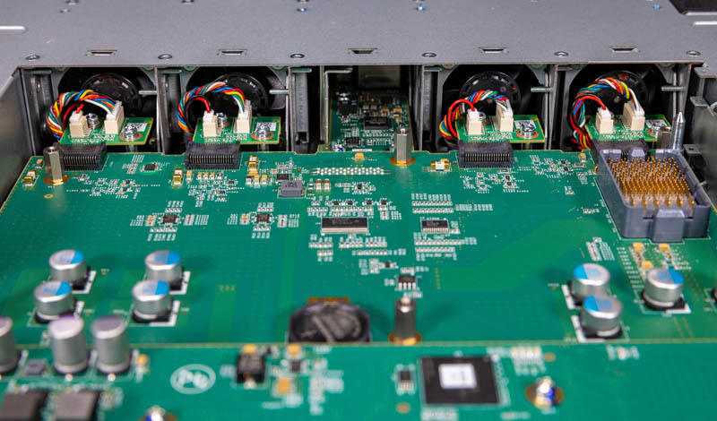
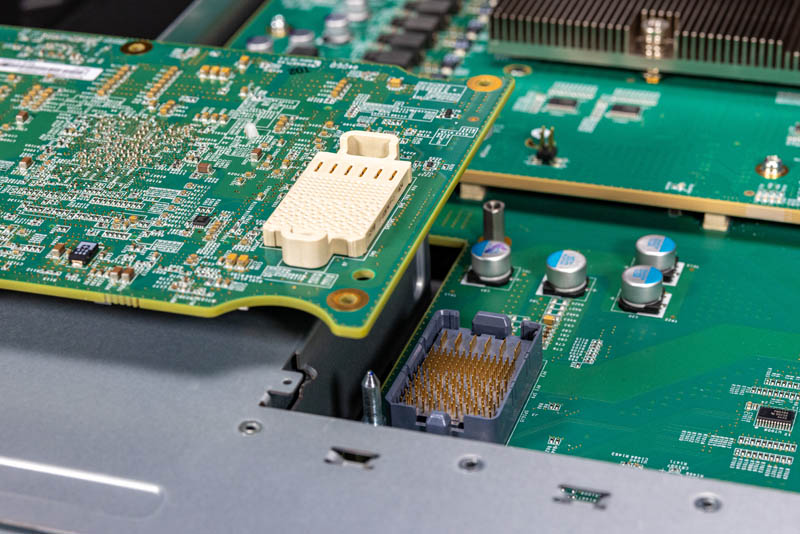
Behind and below the main switch PCB we have a board that ties a lot of the other parts of the switch together. This power and cooling PCB has hot-swap connectors for the fans and power supplies. It also has a high-density connector one can see in the upper right of the below image.
This connector is used to connect the management PCB into the system.
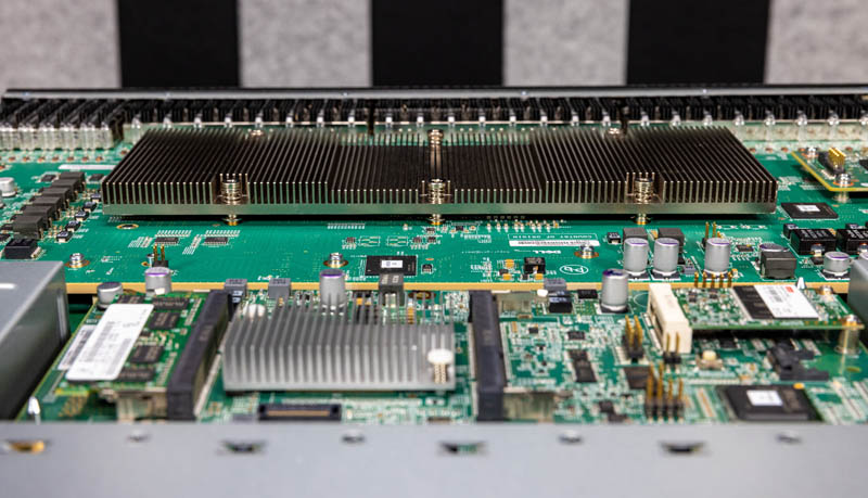
Here is the management PCB occupying the space between the power supplies and in front of the fans.
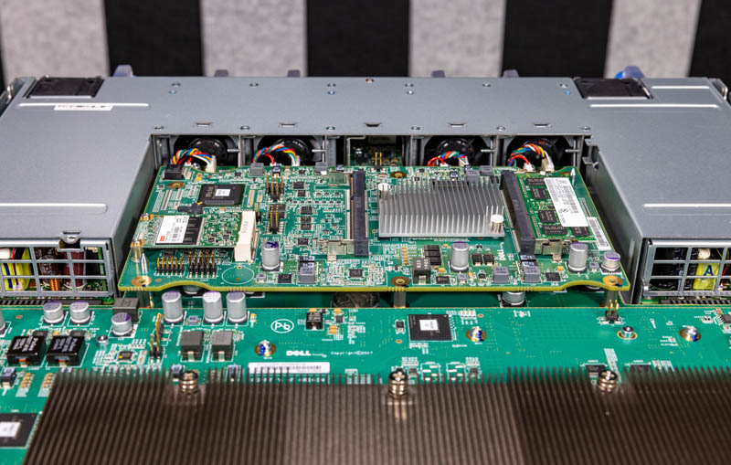
The board itself is the part of the system that runs the Linux-based network operating systems. For those more familiar with servers, this is almost like a small embedded server inside the switch.
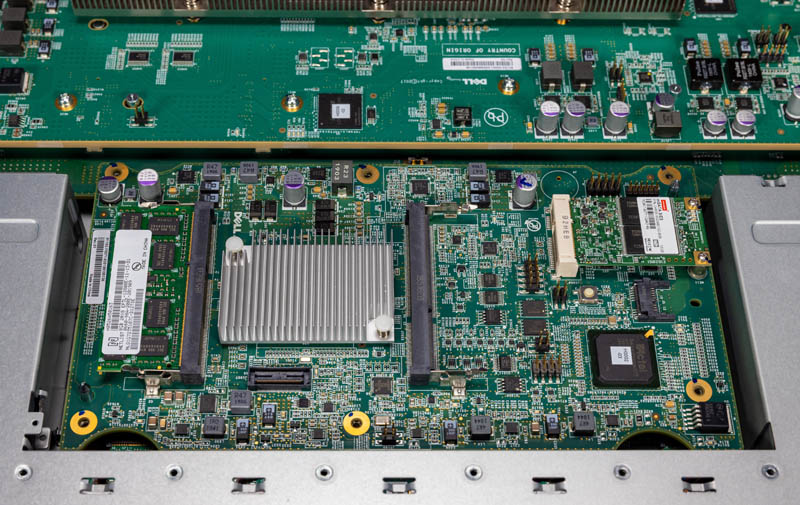
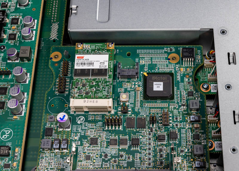
One can see we have the 16GB mSATA Innodisk SSD. We also have an Actel SmartFusion ARM FPGA/ Arm SoC.
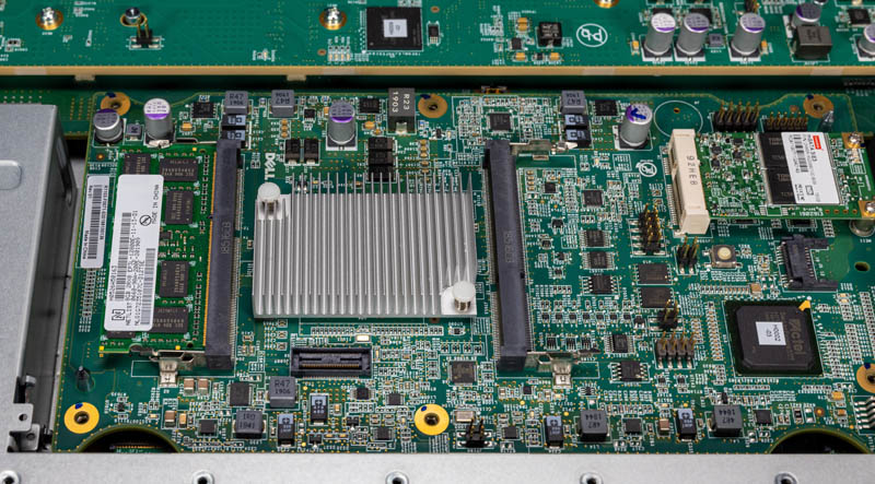
The main CPU compute complex is a quad-core Intel Atom C2000 “Rangeley part”. It is flanked by dual DDR3 SODIMM slots. We have a single 8GB DDR3 SODIMM installed here.
Part of the confusion on this switch may be the quad-core Rangeley processor. This switch, from what we can tell, was released in early May 2017. Timing matters for the Intel Atom C2000 series. There was a major Intel Atom C2000 series bug (AVR54) that would cause systems, over the course of a few years, to not boot. Although STH was hit by this bug in firewalls, there was a solution in terms of a new silicon C0 stepping that came out to fix this as well as a workaround for chips that were earlier stepping.
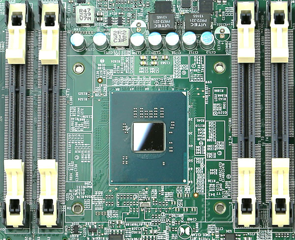
Since the Intel Atom C2000 C0 stepping fixing the AVR54 bug was announced in April, and the bug was first discovered by Cisco and Intel in 2016 (Intel worked with other partners after that), it is highly likely Dell knew of this bug before the May launch date. This is a case where timing matters and our general sense is that these should be OK even though they have Atom C2000 series parts. The market though largely is scarred from pulling switches and firewalls across dozens of vendors and that has given the C2000 series a bad reputation in secondary markets. We wanted to at least address this since the fixes are often overlooked.
Now for the one feature that was not great for service: the CR2032 battery. This battery sits on the PCB that has the power and fan connectors.
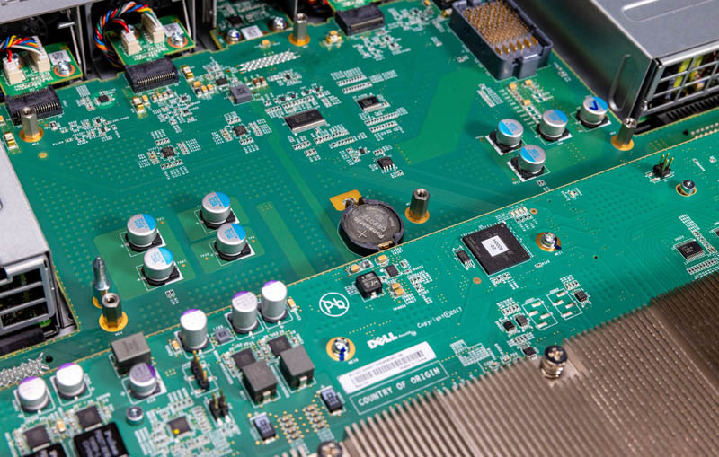
When the management PCB is in place, it is largely obscured. This is a $1 service item in a switch that is very hard to get to.
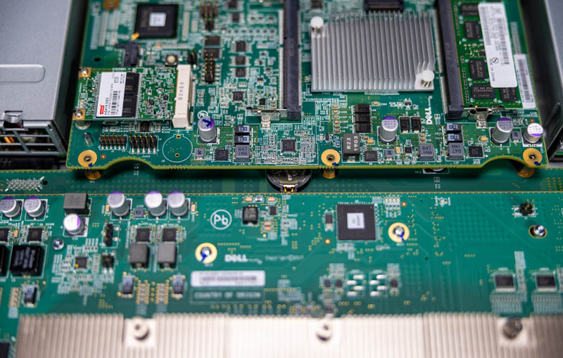
In future generations, Dell rectified this placement but it was one of those areas where it just causes one to pause.
Next, we are going to look at the software implications of this switch’s hardware.


Unfortunately too expensive. But such a 100GBit home network would be great.