How We Could Do it Better (and should for production)
We have a couple of additional single points of failure we could eliminate given a bigger budget. Those things can be added over time in lab usage, but should be considered before doing this in production.
There is a single point of failure between the management interface on the CRS305 and cable in the walls to our MDF. We could solve this in a few different ways. In our example I had already run a second cable, we can simply add a second CRS305 to the mix.
Currently, our network looks like this:
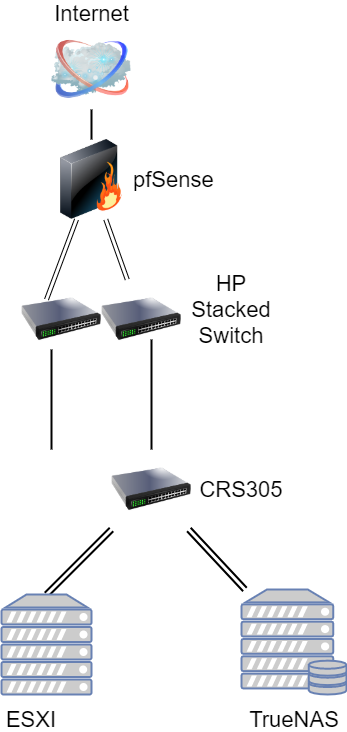
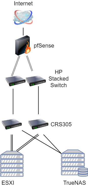
By adding a second switch into the mix we solve the single point of failure problem, both in terms of something going bad in our layer 1 infrastructure, as well as a failure of one of the switches themselves. But also, it allows us to isolate ISCSI traffic from VM guest traffic. This is a leading practice and recommendation from VMWare themselves. In that configuration, we would have a second non-routable subnet/VLAN dedicated to iSCSI, VLAN 101.
Each switch would use VLAN 99 for the MGMT interface. Then we would use VLAN 100 and VLAN 101 for our two ISCSI networks. Each server would have a dedicated port connected to the two different switches. One switch would have a port untagged on the VLAN 100 network, and the other on the VLAN 101 network. These are dedicated layer 2 only networks that do not leave the datacenter. We would then use two additional ports on each switch on the VLAN 99 network. Using VMware vSphere we could create a distributed virtual switch to failover to one or the other switch in the event of a problem. The resulting upgrade would look something like this:
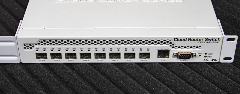
This is only one example of many in which you could improve upon our design. Another possible design choice we discussed in Part 1 was to simply buy a bigger switch to start with, such as the Mikrotik CRS309 (see our review here). In this design, you would create a Link Aggregation Control Protocol (LACP) LAG group. Doing so creates physical redundancy with our uplinks, and for guest traffic in VMWare. It does, however, still leave the switch as a single point of failure.
Another alternative would be to fork out some additional money and buy a pair of higher-end switches. Enterprise-grade switches support stacking, similar to the HP switches we are using. Our community forums have long been filled with people using and loving retired Brocade ICX switches. These switches use a dedicated stacking module with 40GbE ports to do what is called Back Plane Stacking. This method of stacking utilizes additional hardware and often proprietary cables. In the case of the Brocades discussed, they are standard 40GbE DAC cables. This dedicated hardware is used to combine multiple switches into one virtual switch. The additional upfront cost of buying more expensive switches comes with the benefit of physical redundancy and tons of inter-switch bandwidth.

Netgear also has a very cool offering in the high-end SMB space that supports stacking in a half-width form factor. Please read our review of the Netgear M4300-8X8F here. The type of stacking used by Netgear here is different than the type used in the Brocades. It is called Front Plane Stacking, where you utilize ports on the front of the switch to stack them together. This has the benefit of not needing any additional equipment, but you also are limited to the port speed of the interfaces you are using. This creates a possible bottleneck. If multiple devices on stack member A are trying to talk to a device only on stack member B they would utilize most of the inter-switch bandwidth. Additionally, we are consuming ports that could be used for other devices.
Final Words
Now that we have a good grasp on the network all of our components connect to, the majority of the work is complete. We have created a relatively fast and secure network, and have discussed alternative approaches to our recommendations. The remaining work involved surrounds our servers and how we will configure them.
Also worth noting, I do not wish this series to come off as “This is the only way to do this sort of thing”. To borrow from the lightbulb joke:
Question: “How many IT guys does it take to change a lightbulb?”
Answer: “1 to actually do it but 42 more to stand around and say how they would have done it differently.”
The point of this is to show an example approach that can be used or modified depending on your needs. Thank you for making it this far, and we cannot wait to share the next parts where we get into the storage and compute node configuration.

The answer is always 42
The answer, is actually always 420.
You are both correct.
Answer to the Ultimate Question of Life, the Universe, and Everything
Yeah, but does anyone know the actual question?
Some of those add-on fans look like they need safety grilles to prevent loose fingers from being inserted among speedily rotating plastic blades. OUCH!
Yes, better cable management is needed.
Remember, “neatness counts, except in horsehoes and hand grenades”.
Nick, the most common Mikrotik external PSUs can be 24v .8A or 24v 1.2A depending on the market, here in South America the 1.2A is a lot more common on new equipment (rb760igs, lhg, etc) but there is a lot of equipment that comes with the .8A.
Correction: VLAN tagging allows you to carry multiple networks (Broadcast domains) on a single interface. This is often called Trunking. Link Aggregation is combining multiple ports (collision domains) into one logical interface. It is basically NIC teaming for switches. If you can help it use LACP as it fails in a more predictable way
Brian, I am not sure what you are correcting me on?
I believe there is a typo on page 3 under “Configuring our VLANs.” The second port is listed twice, where it should be and where the fourth port was expected.
Thanks for the articles series, I am enjoying them so far.