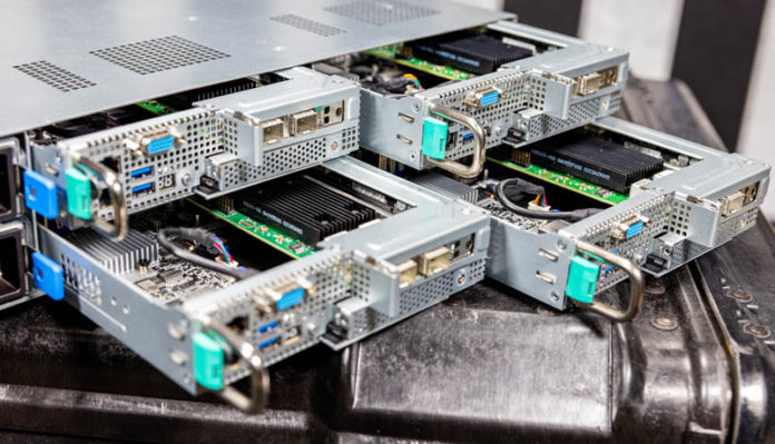
The ASUS RS720Q-E10-RS24 is a 2U 4-node machine, a popular segment for modern servers. This system is based around 3rd generation Intel Xeon Scalable processors, codenamed “Ice Lake” and brings with it a host of new features. This is also a heavily cost-optimized platform. ASUS tends to focus its offerings in this segment on minimizing deployment costs per node. As a result, there are different design decisions that are made in this 2U4N design versus some other segments of the market. Let us get into the review and see how this translates to the server itself.
ASUS RS720Q-E10-RS24 Hardware Overview
Since this is a more complex system, we are first going to look at the system chassis. We are then going to focus our discussion on the design of the four nodes.
ASUS RS720Q-E10-RS24 Chassis Overview
For our chassis overview, we are going to start at the front and work to the rear. The chassis itself is 800 x 444 x 88mm or 31.5″ x 17.48″ x 3.46″. At that depth, it is likely to fit most racks. One will notice that there are 24x 2.5″ drive bays on the front of the chassis and the power button/ LED lights for each of the nodes on the rack ears.
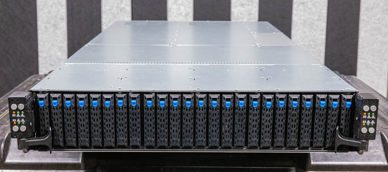
The RS720Q-E10-RS24 has a design feature we have seen on many ASUS servers, but not many others. Specifically, because the four nodes take up most of the rack ears, ASUS adds little handles on each side to help move the chassis in and out of a rack.
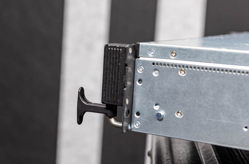
The drive configuration is 24x 2.5″. That includes eight bays that can accommodate NVMe SSDs. All 24x bays can support SATA or SAS with a RAID controller/ HBA add-on. Some 2U4N chassis support all NVMe but that requires a lot more on the connectivity side than this approach. For many markets, these systems have only 1-2 drives so this helps to keep the costs down.
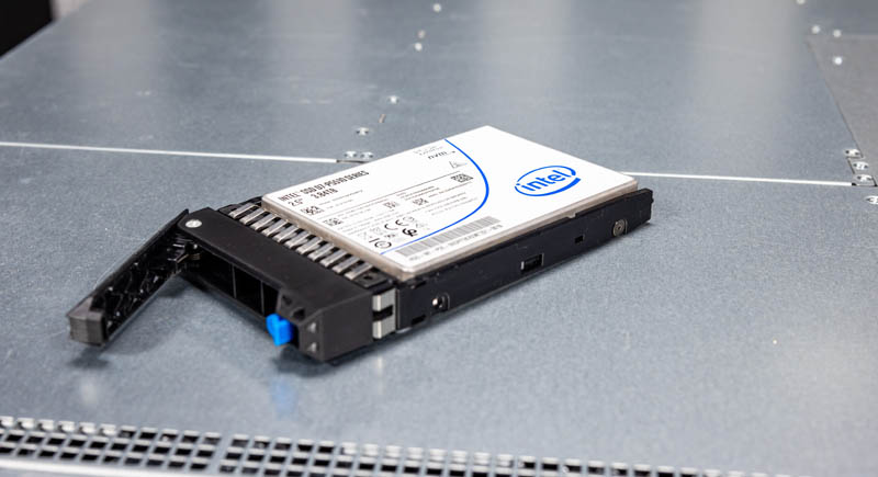
When we discuss cost optimization, our review unit still had the older drive trays that utilized screws instead of being screw-less designs.
The chassis itself has a nice feature. Specifically, it has a middle access panel. One can pull the chassis part of the way out from the rack and open this panel to get to the main chassis functions (the storage backplanes are under the front panel.)
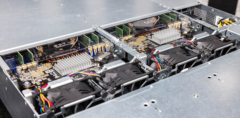
Here we can see a few things. Perhaps the most important are the five fans. Four of these fans are large Delta units that cool the chassis. Some 2U4N designs use common chassis fans like these to achieve better efficiency. Some 2U4N designs use smaller fans on each node tray to make them easier to service. ASUS’s design here is the higher efficiency option. Something that is a cost optimization is that the fans are not in hot-swap carriers. Those carriers add cost but make it easy to swap fans. Then again, to do a fan replacement, these chassis often need to be taken offline anyway. Fans are very reliable, but every so often this does happen.
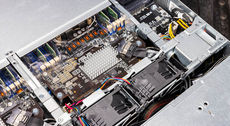
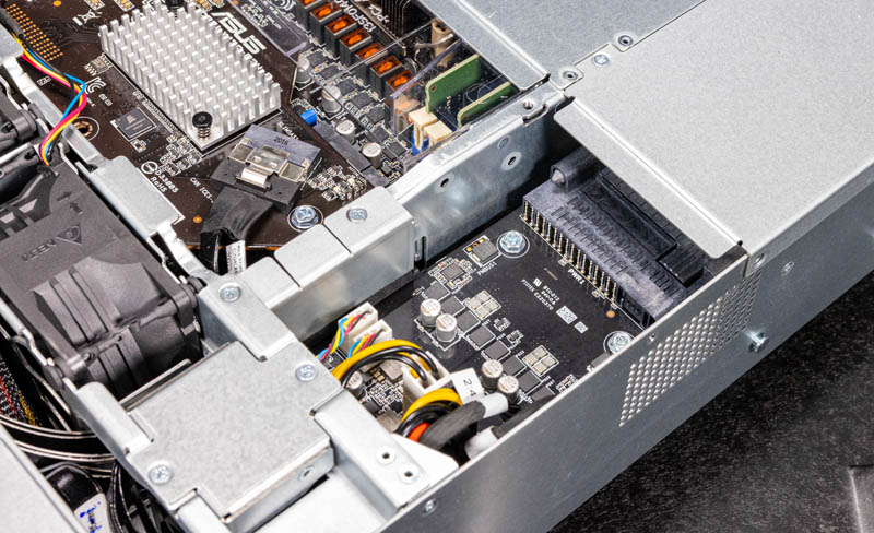
One will also notice the boards used to mate the node to the chassis. This is where the nodes are powered and have data connections to the drives up front.
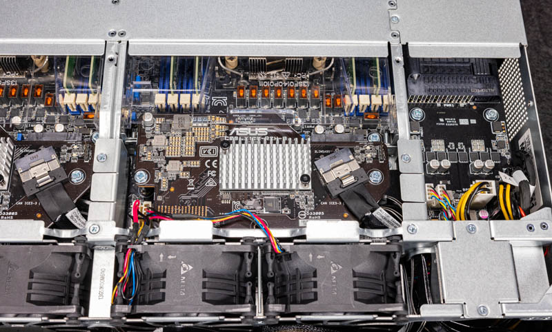
On the right side of the chassis, we have the power distribution board. On the front of the board, there is actually a fifth smaller fan held in place on a metal carrier with two small screws.
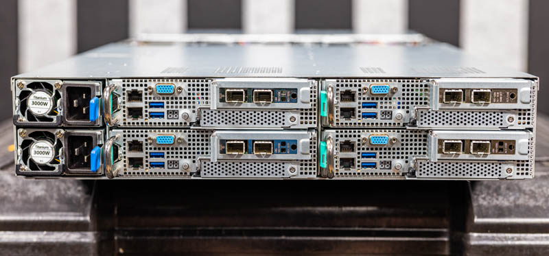
On the rear of the chassis, we get two power supplies and four nodes. We are going to focus on the nodes in the next section.
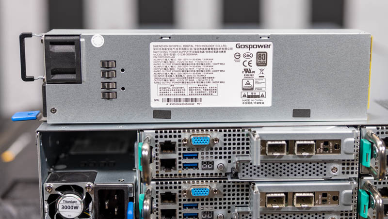
The power supplies are Gospower 3kW 80Plus Titanium units.
One of the main functions of the chassis is to hold and provide access to the four compute nodes.
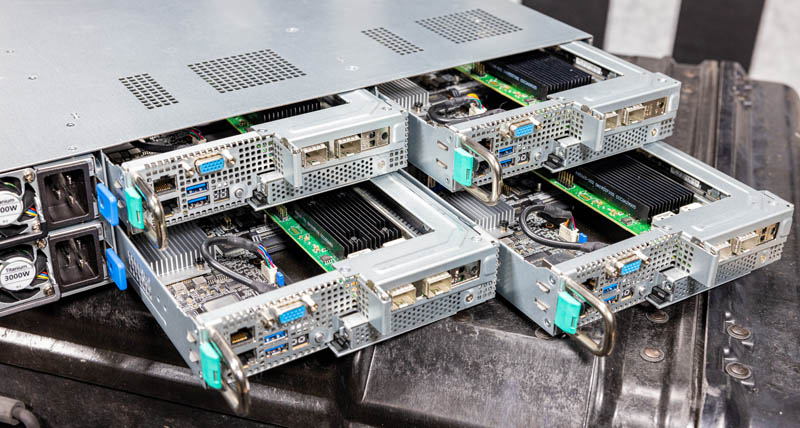
One small area of improvement is the latching mechanism for the nodes. The way the power supplies are oriented, the tabs for the center nodes are very close to the power supply retention tabs.
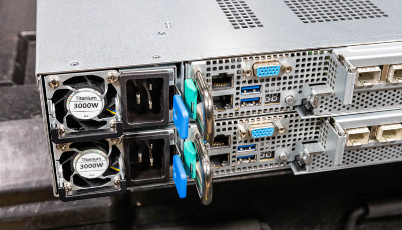
This is made a bit more challenging by the fact that the teal node tabs use large screws to hold them in place.
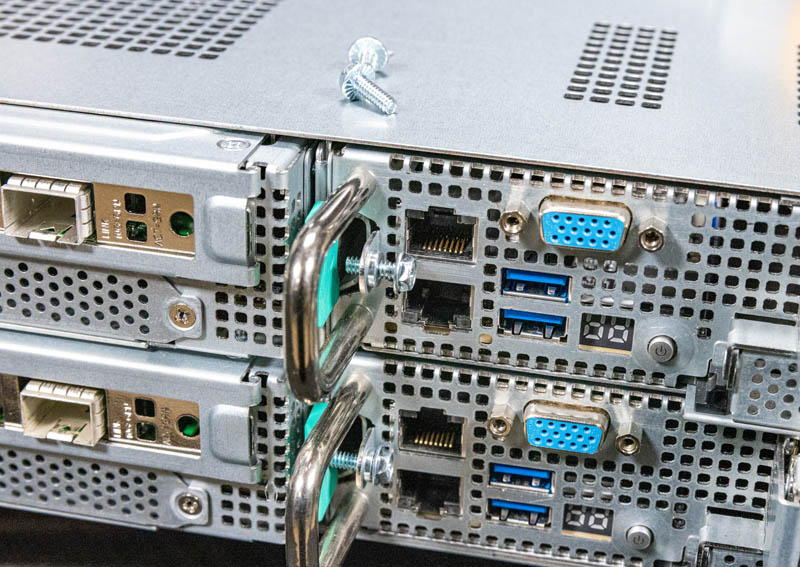
This is one of those cost optimization areas where it would cost more to have a fancier retention design in the chassis, but ASUS is focused on providing lower-cost nodes.
Next, we are going to get to those nodes.

