ASUS RS720A-E11-RS24U Internal Overview
Opening up the top panels, we can see inside. There is a fan partition but behind that instead of seeing CPUs, memory, and risers, we see these large metal cages. We will get to those soon.
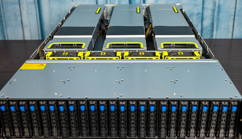
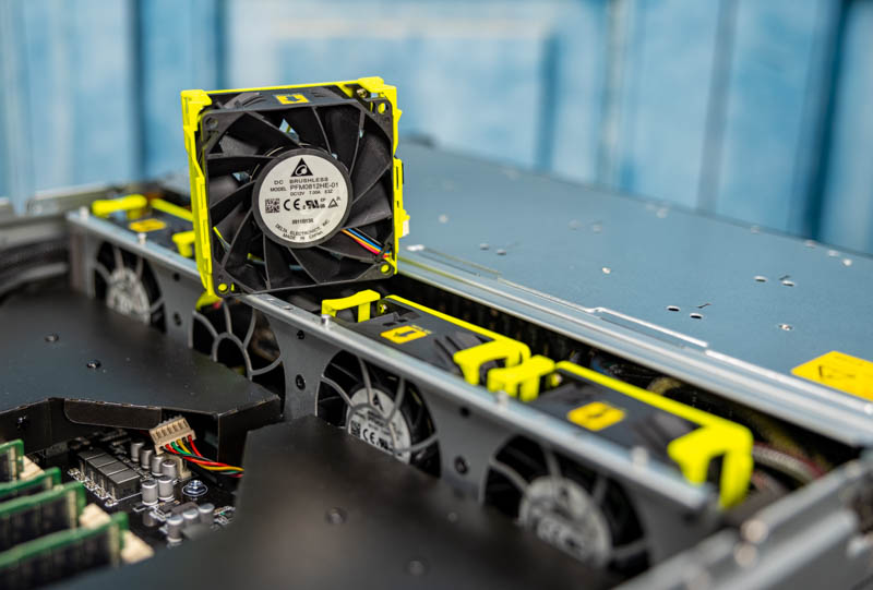
On the fan side, we have four hot-swap delta fans. The fans along with the GPU cage/ riser handles are in a bright green/ yellow color to show they are places that are designed for hands-on service.
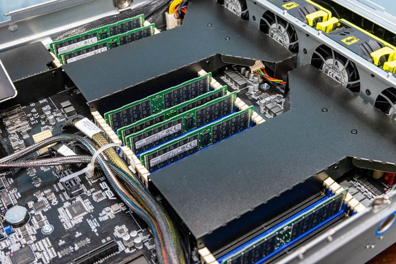
The key to this system is that with the GPU configuration, it is designed to have two distinct airflow segments. One on the top of the chassis, the other is on the bottom. This bottom part is where we see the dual AMD EPYC 7003 CPUs. The specs of the motherboard say up to 225W TDP support, but we have 280W AMD EPYC 7763 CPUs in this system and that is how ASUS configured it. These give us a total of two 64-core/ 128 thread (128C/ 256T combined) processors for the high-end processors of today. You can see our AMD EPYC 7763 review to learn more.
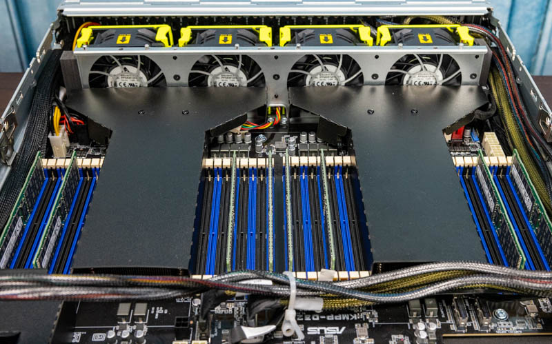
On the memory side, we get 32x DDR4 DIMM slots. Our system came equipped with 8x 64GB DIMMs, but we swapped those out to 16x 32GB DIMMs for our testing to fill memory channels. Still, for photo purposes (since we were tight on DIMMs in the lab given the back-to-back EPYC and Xeon launches) we used the configuration that ASUS loaned us the system with. Each CPU can support up to 16x 256GB DIMMs for up to 4TB per socket or 8TB in the system.
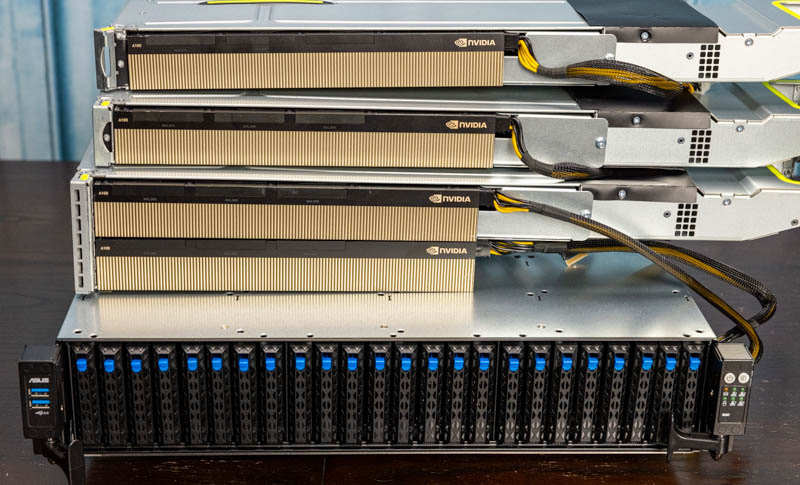
On the subject of those large GPU cages, you can see the three of them here, and two of the NVIDIA A100’s installed. Check the accompanying video to see how they are removed.
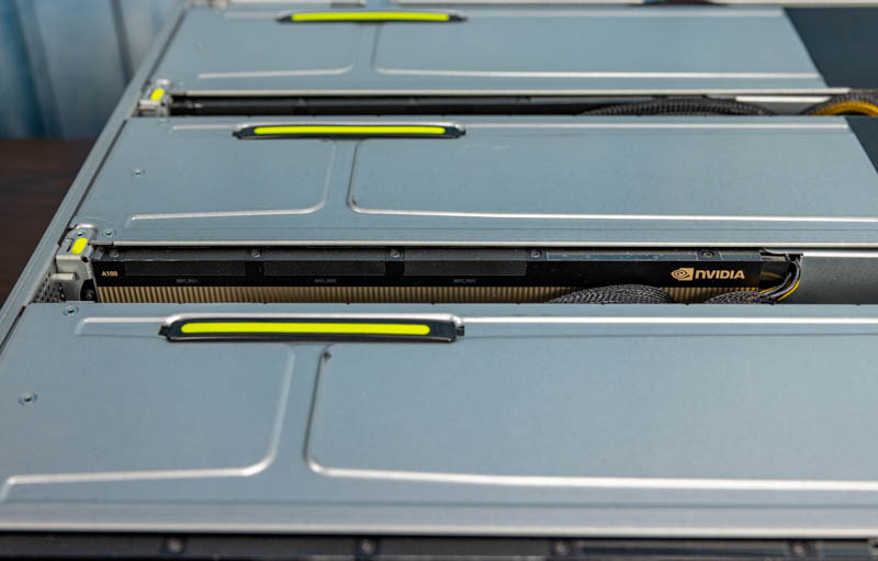
A key reason we are calling these cages, instead of risers, is that they are independent units. Each is secured into place, but PCIe is provided via two x8 connections on the motherboard instead of via a traditional slot and riser (except for the dual GPU riser which is a combination.)
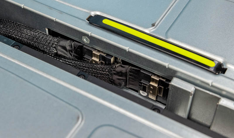
This is a more modern approach since it allows easier servicing and more freedom in where GPUs can be placed in a system. It also allows the flexibility to offer a more traditional riser setup, or to have these large GPU cages.
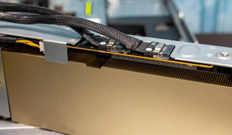
The PCIe cables then have a PCIe Gen4 x16 edge connector that connects directly to the GPU.
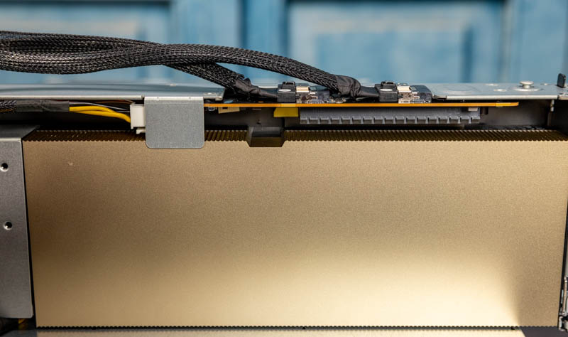
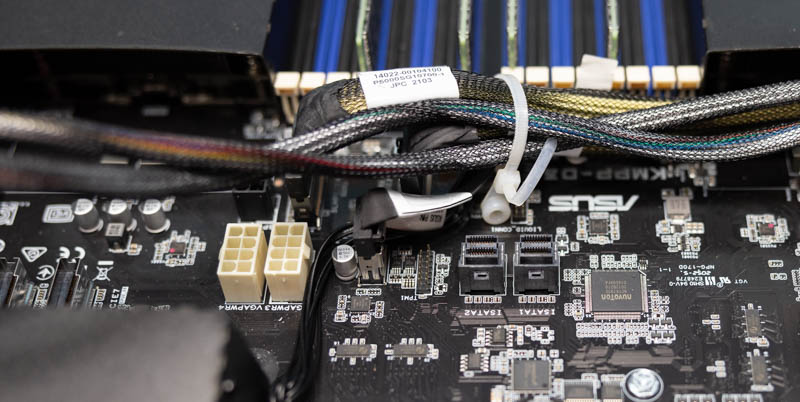
The PCIe x8 cables are then connected to motherboard connectors. One can see how much denser these connectors are than traditional PCIe x16 edge connectors. That helps in system flexibility.
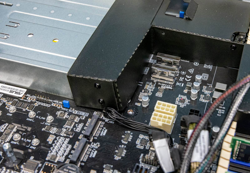
Next to these PCIe connectors, there are GPU power headers on the motherboard. Something one may notice is that the board in these cages also has power. Power is provided to the GPUs directly in each of the cages.
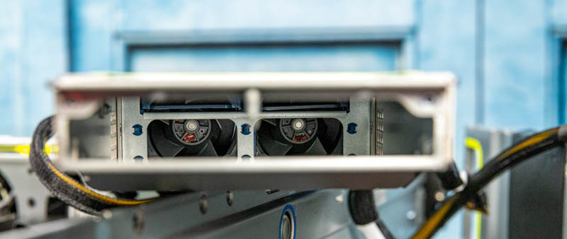
Power from the cable can also be used to spin fans in the GPU cage assemblies. Here is a shot inside one of the assemblies with two fans to keep the accompanying GPU cool.
As a quick note here, we are showing the NVIDIA A100 40GbE PCIe cards here, but these could just as easily be accelerators like GPUs from AMD, FPGAs from Xilinx/ Intel, or other accelerators. The advantage of PCIe is that it is flexible because in the data center cards are designed to standard power and dimensions.
On the motherboard, we get two M.2 slots. We see these mostly being used for boot media and two means we can potentially mirror a boot drive across two physical drives.
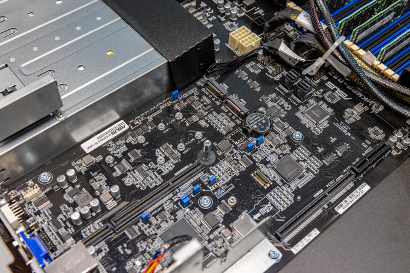
Above this area, we have another riser that we looked at earlier. Onboard there is the standard networking. The other side of this riser has the ASUS PIKE II controller. This example is a Broadcom/ Avago/ LSI SAS3108 RAID card, but there are HBA options as well.
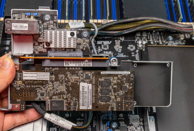
This card is then connected to the front of the chassis to provide SAS3 and RAID connectivity. Since these are SFF-8643 cables, there are also onboard motherboard SATA connectors that can be used to free up this low-profile slot.
If we were configuring a system like this, we might look at a 100GbE adapter or a NVIDIA-Mellanox BlueField-2 DPU instead of the RAID card.
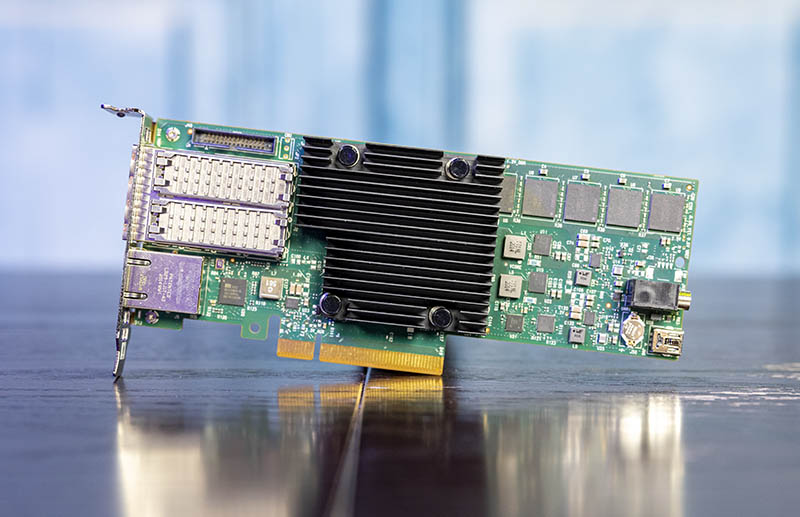
The ability to have an Arm-based system with crypto-offloads and capabilities to manage NVMeoF for a high-end machine like this would fit better in our infrastructure than the PIKE II controller. The key though is that using a PIKE II controller for SAS3/ RAID would mean that one does not have rear I/O available for higher-end networking. That would leave only the dual 10Gbase-T as the networking option which is a bit less balanced when there are four NVIDIA A100 GPUs. Again, we have more views of pulling the GPU cages from the system in the accompanying video which may help if you are having trouble visualizing.
Next, we are going to look at the management of the system.

You guys are really killing it with these reviews. I used to visit the site only a few times a month but over the past year its been a daily visit, so much interesting content being posted and very frequently. Keep up the great work :)
But can it run Crysis?
@Sam – it can simulate running Crysis.
The power supplies interrupt the layout. Is there any indication of a 19″ power shelf/busbar power standard like OCP? Servers would no longer be standalone, but would have more usable volume and improved airflow. There would be overall cost savings as well, especially for redundant A/B datacenter power.
Was this a demo unit straight from ASUS? Are there any system integrators out there who will configure this and sell me a finished system?
there’s one in Australia who does this system:
https://digicor.com.au/systems/Asus-RS720A-E11-RS24U