ASUS ESC8000A-E13P Internal Hardware Overview
The top section we will get into a big, but there is a motherboard underneath the front top section.
Since we were at ASUS in Taipei, and we had limited time and a fully configured system, I asked if someone had an extra motherboard. They did, so here is where the motherboard goes in the system, just behind the front bottom fans.
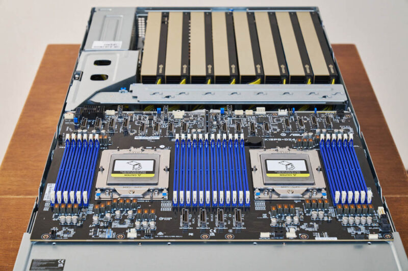
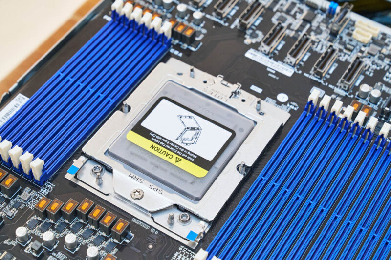
This is a dual AMD EPYC 9004/ 9005 socket SP5 system. We get 12 DDR5 DIMMs per CPU for 24 total.
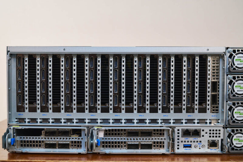
The rear of the motherboard has a slew of MCIO x8 connectors.
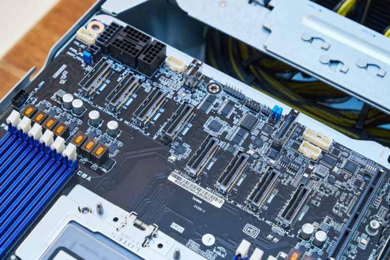
You can see the rear of the ASUS K15PG-D24 motherbaord is almost all MCIO connectors.
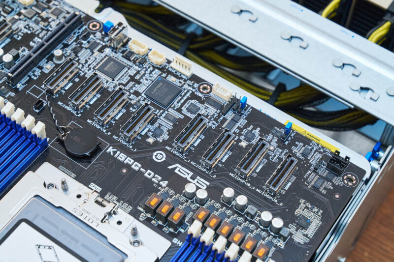
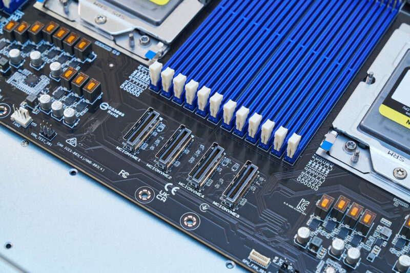
There are also four at the front of the board.
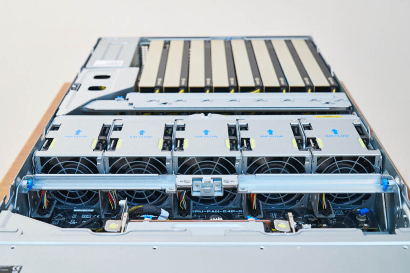
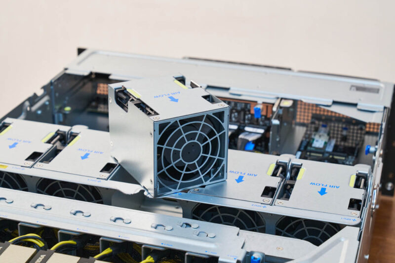
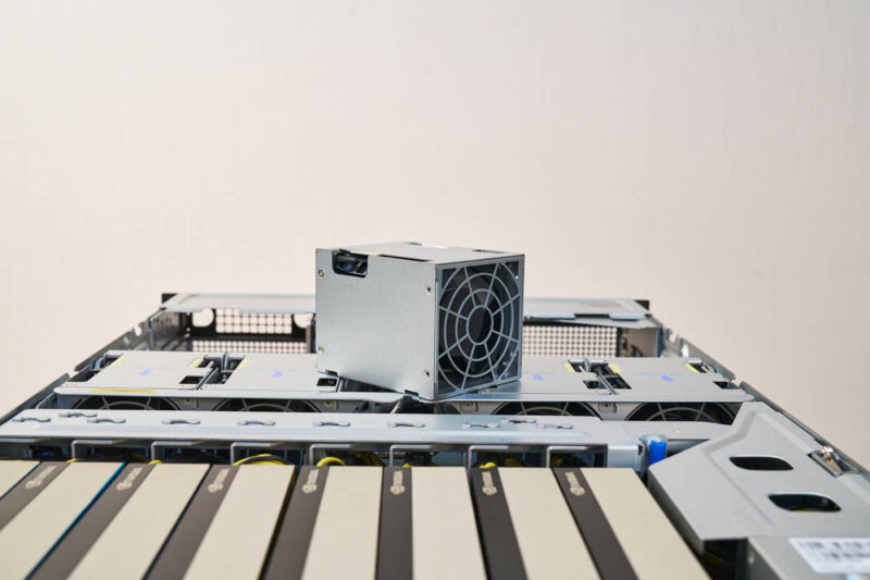
At the top of the system, we have five fan modules.
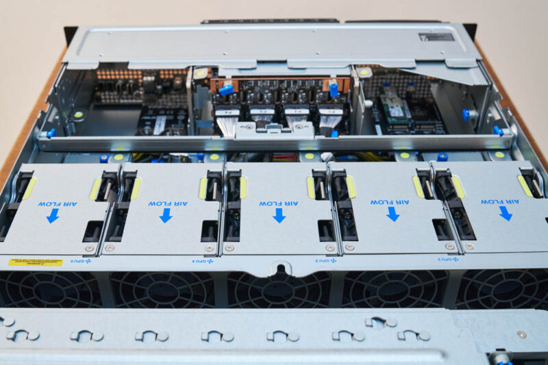
These are the fan modules designed to cool the GPUs.
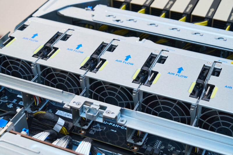
The fan modules are very easy to swap.
A reason for this is that they connect into a GPU fan board designed to deliver power to the fans.
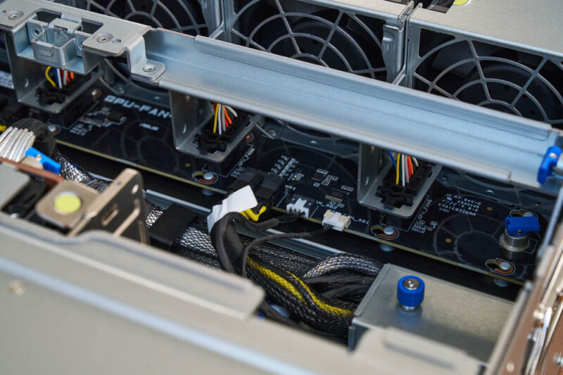
A neat feature is that, like most of this system, the fan power board is held in place by tool-less latches and pins.
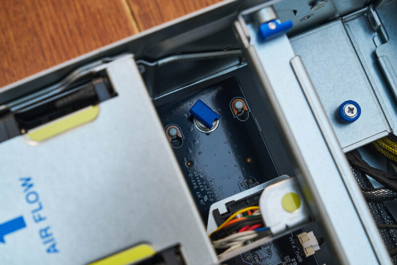
Overall the fan partition is quite easy to service.
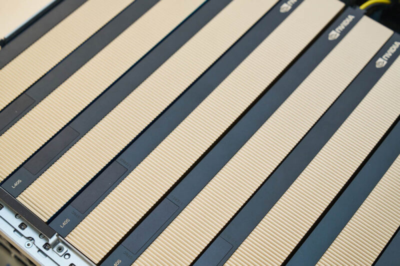
Between the fans and the GPUs is a retention bar that keeps the GPUs in place and helps keep the power cables for the GPUs routed neatly.
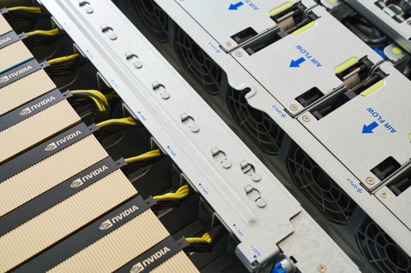
Behind this bar are the GPUs. Here we have eight NVIDIA L40S GPUs, each with 48GB of memory.
The “P” seems to denote that this is a PCIe switched architecture, which helps us get more lanes than the non-P version for cards.
Next, let us get to the topology of the system.


I like that this one’s got the PCIe switches better because it’s got more slots for NICs. I’m not totally behind just having 32 Gen 5.0 lanes back to the CPU.
There is a flaw in the block diagram, the DIMMs run from the PCIe switches in stead of the CPU’s.
I assume this is not a CXL solution (12 DIMMs through 32 lanes PCIe Gen5) ;-)