A few months ago, we showed you the ASRock Rack GNRD8-2L2T. Over the last few weeks, we have been using one. The ASRock Rack GNRD8-2L2T is a single-socket Intel Xeon 6 motherboard with a lot going for it. There is a lot of connectivity, onboard features, and caveats, making a review a lot of fun. Let us get to it.
ASRock Rack GNRD8-2L2T Overview
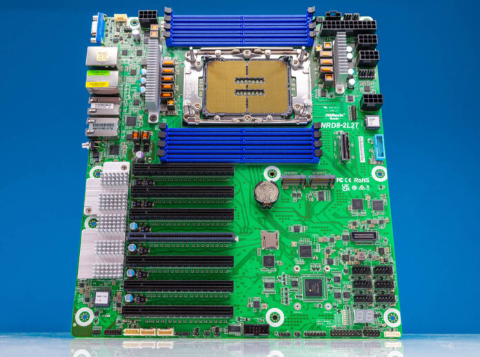
The GNRD8-2L2T is a fairly large motherboard. It is a CEB (12″ x 10.5″) motherboard and that is becoming very common even for single-socket platforms. Modern server platforms have too much I/O for a standard ATX form factor.
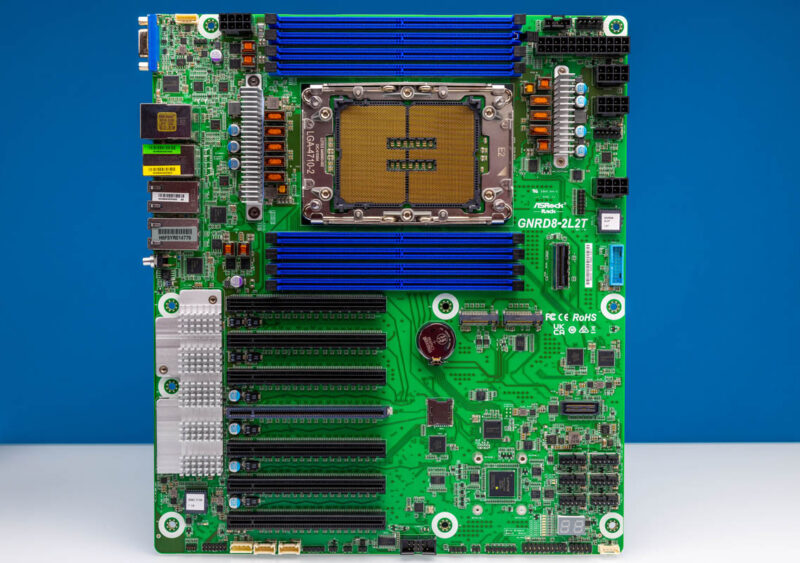
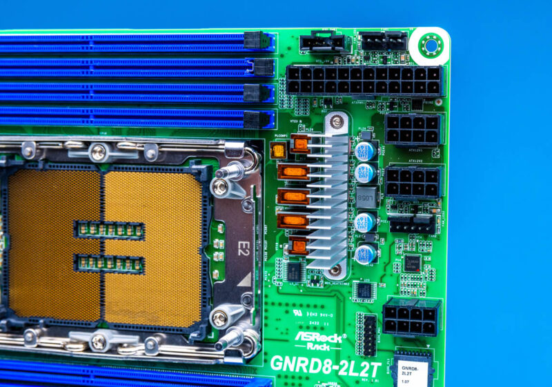
The socket is the Intel LGA4710. Currently, this is a Sierra Forest or Intel Xeon 6700E series socket. In Q1 2025, we should see the Granite Rapids-SP or the Xeon 6700P series which we expect will also work in this platform. We already discussed the Intel Xeon 6 R1S is a Single Socket Special, and this board feels like it is designed for the extended I/O CPUs.
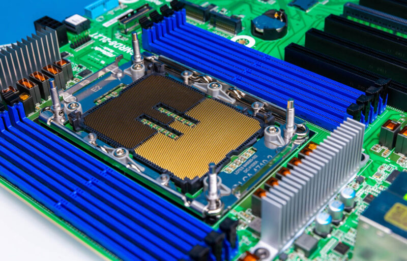
Flanking the socket are eight DDR5 DIMM slots. This is a 1 DIMM per channel (1 DPC) configuration even though the Xeon 6700 series is 2 DPC capable. Adding another eight DIMM slots would simply take too much space.
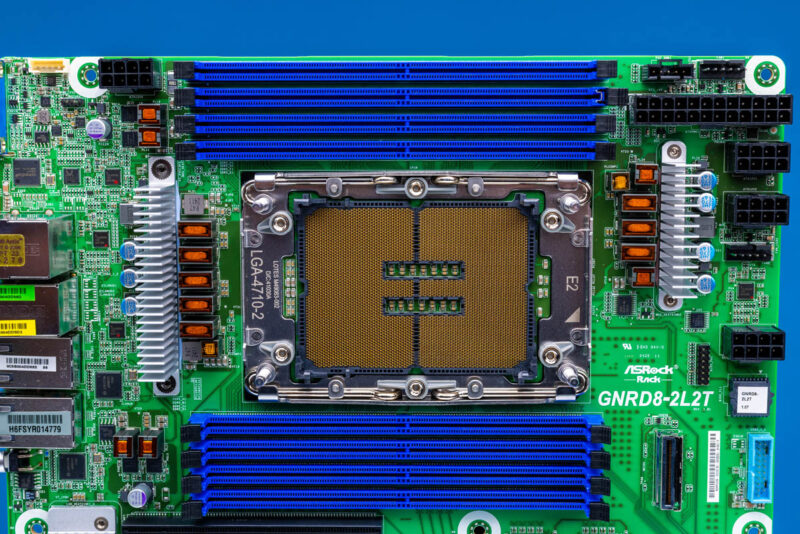
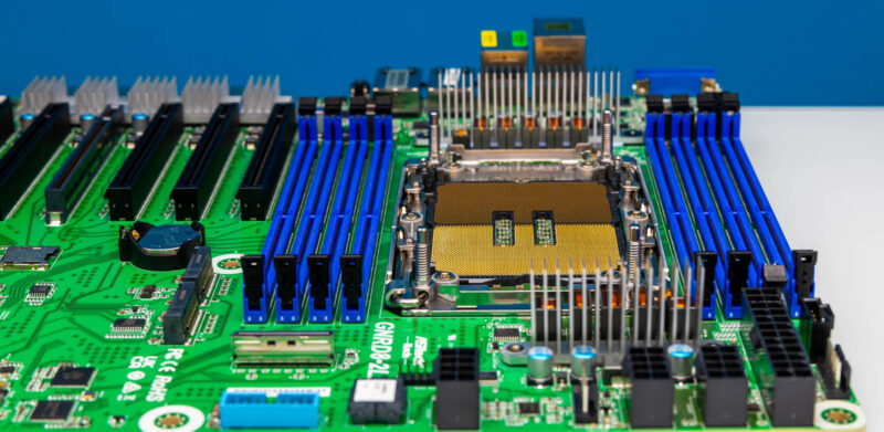
Of course, the socket and DIMMs are aligned front to rear for a standard airflow in most servers and higher-end workstations.
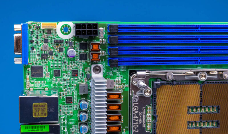
Power input is crazy. There is a standard ATX 24-pin power input along with three of the four 8-pin power inputs on the top right side of the motherboard.
Below that area, we get a MCIO connector as well as a USB 3 front panel connector.
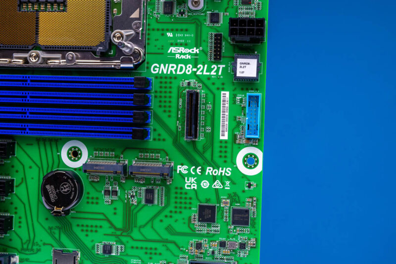
The bottom right portion of the motherboard has lower profile components to help with fitting long expansion cards.
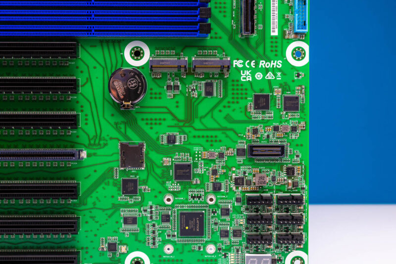
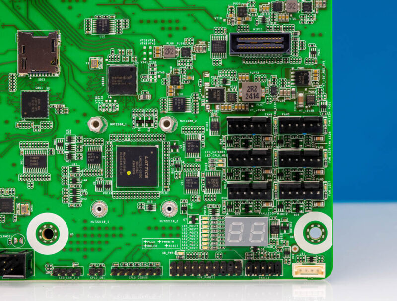
On the bottom right, we have an array of fan headers as well as a POST code status display.
In terms of storage, we get two M.2 slots that can be M.2 2280 (80mm) or 22110 (110mm.) Something we wish ASRock Rack did was to use tool-less retention mechanisms instead of thumbscrews.
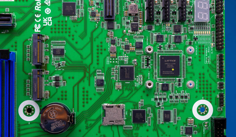
If you are wondering, that is a microSD card slot next to the battery.
The feature many will want to see is the array of PCIe Gen5 x16 slots. There are seven of these slots on the motherboard. Depending on the CPU, not all of them are active. We will get to that in our block diagram discussion.
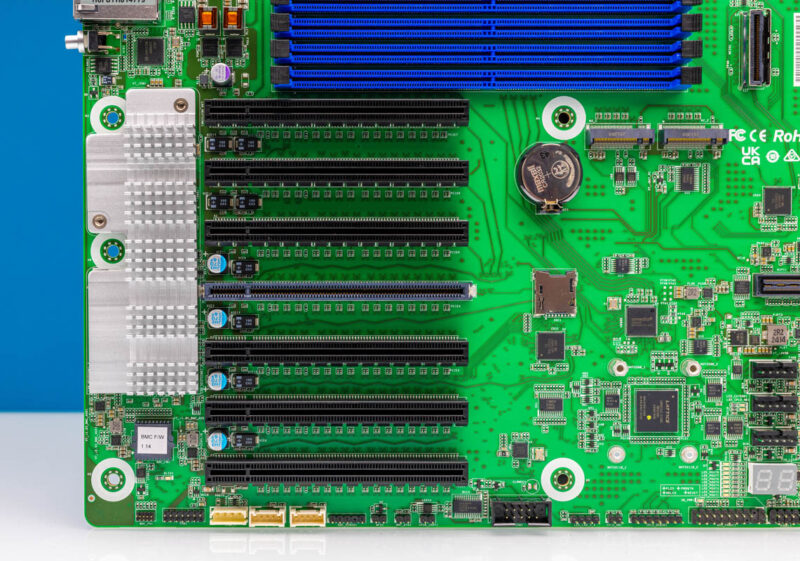
The big heatsink has the ASPEED AST2600 BMC as well as the Intel X710 onboard 10GbE NIC.
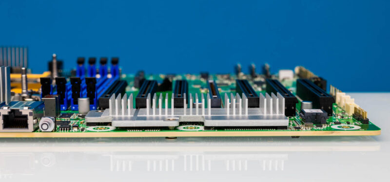
Looking at the profile of the board, one can quickly see that everything is placed for front to rear airflow orientation.
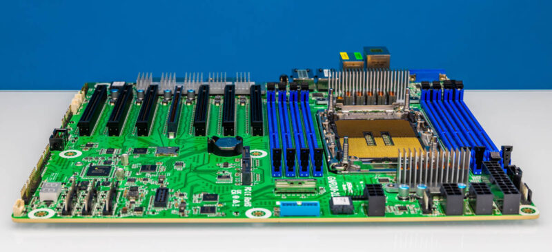
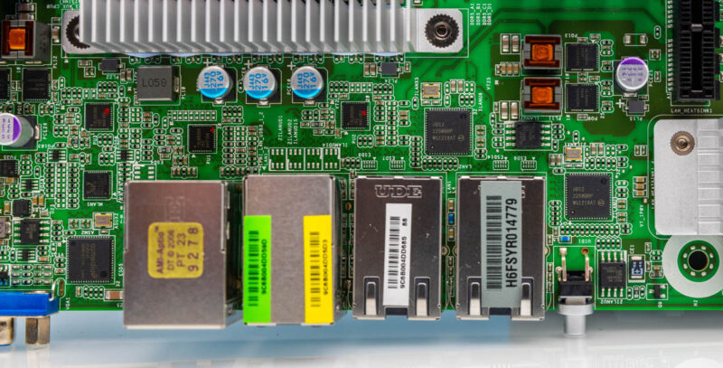
In terms of rear I/O, we have a VGA port, two USB 3 ports, a management port, and then four NIC ports. The four NIC ports are two 1GbE and two 10GbE with the 10Gbase-T ports being powered by the Intel X710 under the heatsink near to the PCIe slots.

The 1GbE ports use two Intel i210 NICs that sit behind some of the ports.
In the top left, we have the fourth 8-pin power connector.
Next, let us get to the block diagram.

There is some sort of connector directly above the fan headers shown both in your photos and asrocks but missing from the manual, it’s mentioned in the 3d models as a 60 pin board to board connector but i’m not sure what it would be used for(i’ve seen dell do something similar for modular idrac but this is in the wrong location) Any idea what it is for?
@Daniel Smith
Based on the component designators silkscreened onto the solder resist, I’m guessing that’s a MIPI port for something. What, I have no clue. It’s actually marked “MIPI1” if you look closely at the board in the larger photo.
How long does it take to POST? It would be nice if eliminating the PCH improved boot time.
Boot times….isn’t it the BMC that makes server board boot times so long?