
The ASRock Rack 4U8G-TURIN2 offers a refreshing take on a classic AI server design, taking advantage of AMD EPYC CPUs to deliver something different. Of course, since this is an ASRock Rack server, we also get some unique bits of server engineering. That makes this a fun one to look into.
For this one, we have a video shot by our new cameraperson, Sam:
We always suggest opening this in its own browser, tab, or app for the best viewing experience. As you might imagine, ASRock Rack sent the server, AMD sent us CPUs, Broadcom and NVIDIA NICs, NVIDIA GPUs, Astera Labs CXL memory expansion modules, and so forth, so we have to say this is sponsored.
ASRock Rack 4U8G-TURIN2 External Hardware Overview
The system itself is a 4U server at 786mm or just under 31 inches deep.
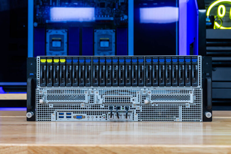
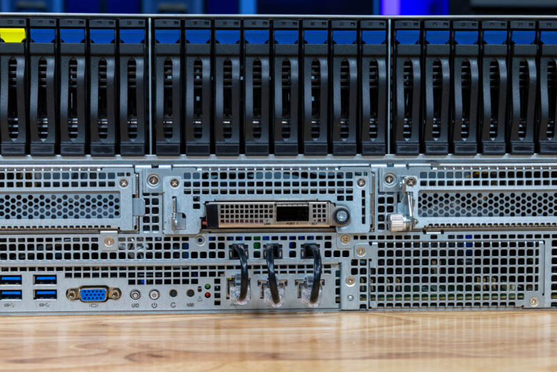
The top 2U of the server is filled with 2.5″ drive bays, and the first four are NVMe.
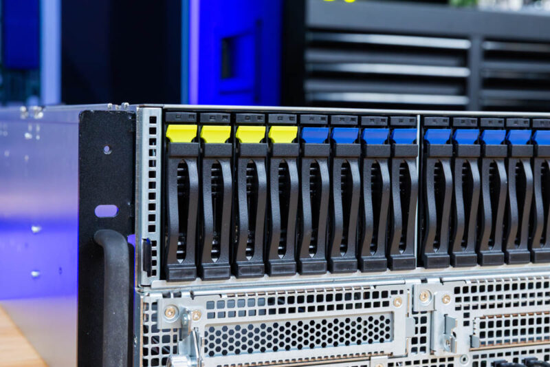
We were able to put Kioxia CD6 and CM6 SSDs in this and the drive trays are tool-less designs making them easy to install drives into.
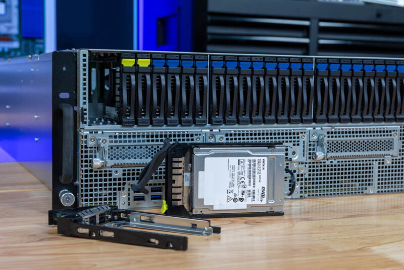
You will see that the backplane is populated, but there is a lot of room for airflow around the drives.
Something that you may not know, just by looking at the front, is that these 20 additional drive bays have the ability to be SAS/ SATA if a SAS controller is added, or NVMe, if additional lanes via MCIO cables are provisioned. They are just not hooked up by default in this server since the connectivity is focused on the GPU area.
Below the NVMe drives is a full height expansion cutout then the front I/O with four USB 3 Type-A ports and a VGA port.
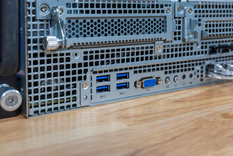
Keeping true to ASRock Rack’s design language, and something we saw on the ASRock Rack 6U8X-EGS2 H200 NVIDIA HGX H200 AI Server is that there are cables plugged into the front network ports. There are two 1GbE ports powered by an Intel i350 and then an out-of-band management port. If you want to wire these into front networking, then you can just remove the chassis ones and use them there. We will show you where these go to in the rear of the system shortly.
On the right hand side there is another full height expansion slot.
That brings us to the enter OCP NIC 3.0 slot. The three front middle expansion slots are wired for this to be a PCIe Gen5 x8 slot with an additional x8 connection to one of the NIC slots. You can move MCIO cables and turn this into an x16 slot for a 400GbE NIC as an example.
Throughout this server we are going to talk a lot about flexibility. This is a great example with the empty MCIO storage connectors on top, the SAS/SATA connections below, and then one of the two MCIO x8 ports plugged into the OCP NIC 3.0 slot.
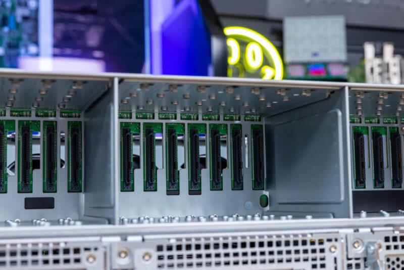
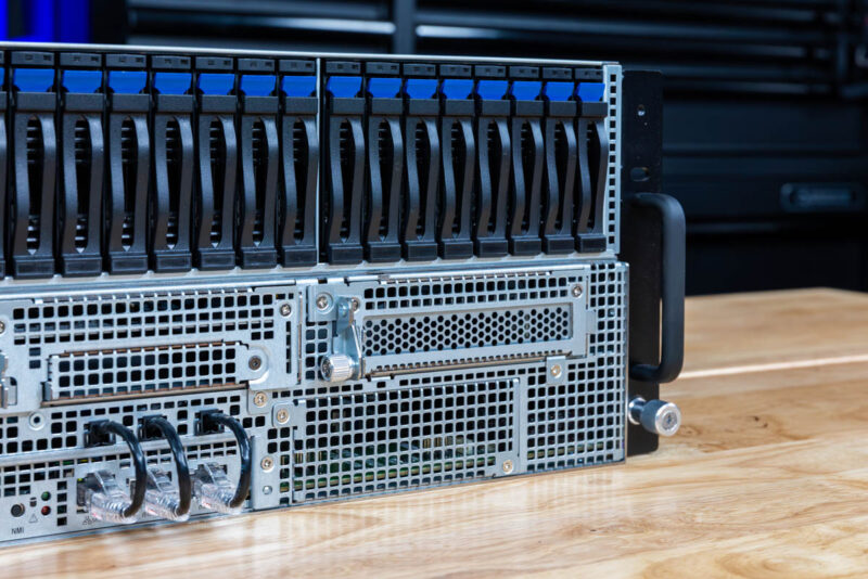
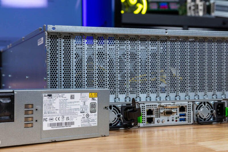
Moving to the rear of the system, and it becomes obvious that this is designed for PCIe expansion cards.
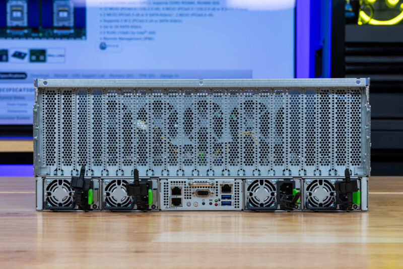
The entire top 3U of the server is just expansion card slots.
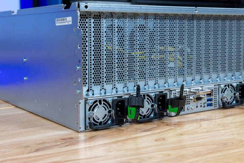
On the bottom, we have four power supplies. These are supposed to be 2.7kW 80Plus Titanium PSUs per the spec sheet, but we have a very early sample of this server, so these are 2kW 80Plus Platinum units. That extra 700W per PSU is important if you are running high-end cards in the system and want to maintain redundancy.
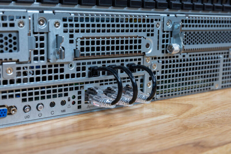
On the rear I/O, we can see the VGA port and pair of USB ports. The three network ports for management and 1GbE connectivity are fed via the cable that we saw at the front of the chassis. So if you want to wire these in the rear, you can simply keep those network cables connected.
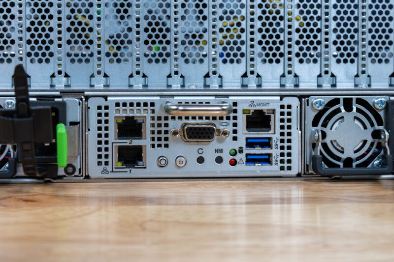
If you were so inclined, you could have a management port in front, and 1GbE ports in the rear, or you could have a rear management port and one 1GbE port with a single 1GbE port up front. It seems like a simple solution, but it also gives the system a lot of flexibility.
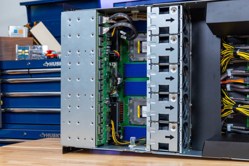
Next, let us get inside the system to see how it works.


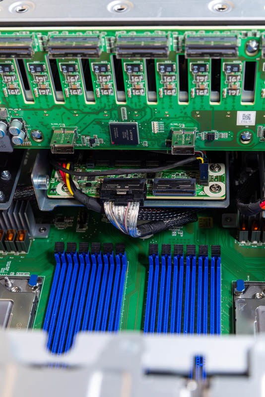
> two M.2 slots under the 2.5″ storage and PCIe expansion slots on the motherboard. These are lower speed PCIe Gen3 x2 slots
According to the block diagram these are Gen 3 x4 slots, although the first one had a rather interest lane arrangement where one lane is reused for a SATA controller if SATA m.2 SSDs are used.