The Gigabyte MC62-G40 is a cross between a server and a workstation motherboard. The motherboard itself is designed to take AMD Ryzen Threadripper Pro CPUs and provide a capable computing platform in either role. In our review, we are going to take a look at one of the many Threadripper Pro systems we have been reviewing, but this one is unique in its focus on being quite server focused as well.
Gigabyte MC62-G40 AMD Ryzen Threadripper Pro Motherboard Review
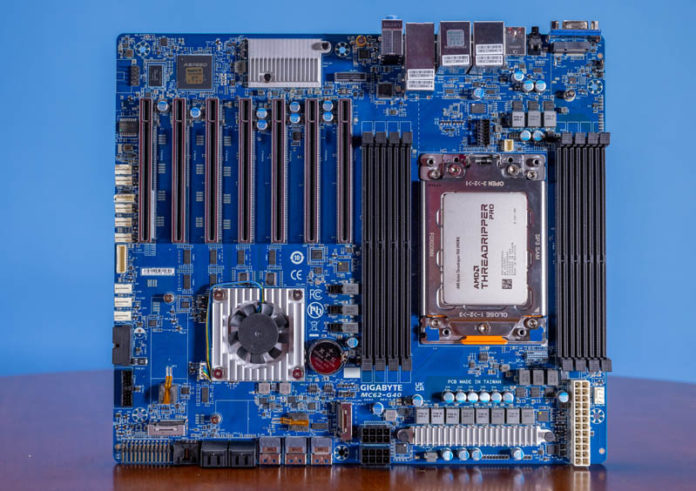
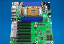
The Gigabyte MC62-G40 is a CEB 305mm x 267mm motherboard. For this generation of boards, this platform is relatively compact. One of the big features of this platform is that it is a form factor that can fit into many form factors whether they are server or workstation.
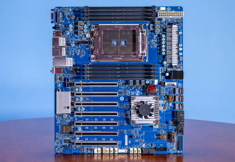
The sWRX8 SP3 socket is designed for AMD Ryzen Threadripper Pro 3000 and 5000 series processors.
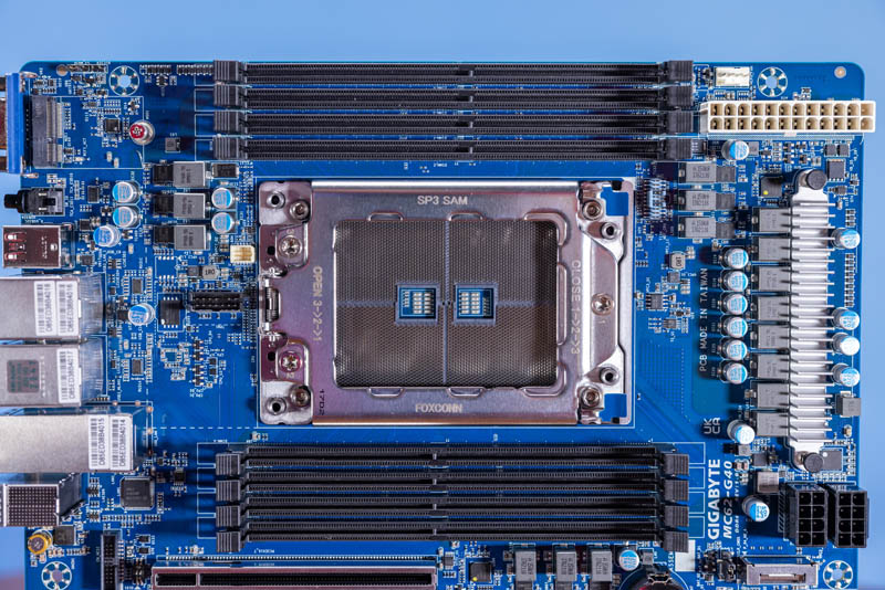
We showed this in our Threadripper Pro 5995WX review. That means one can get up to 64-cores of “Milan” generation Zen 3 cores on this platform.
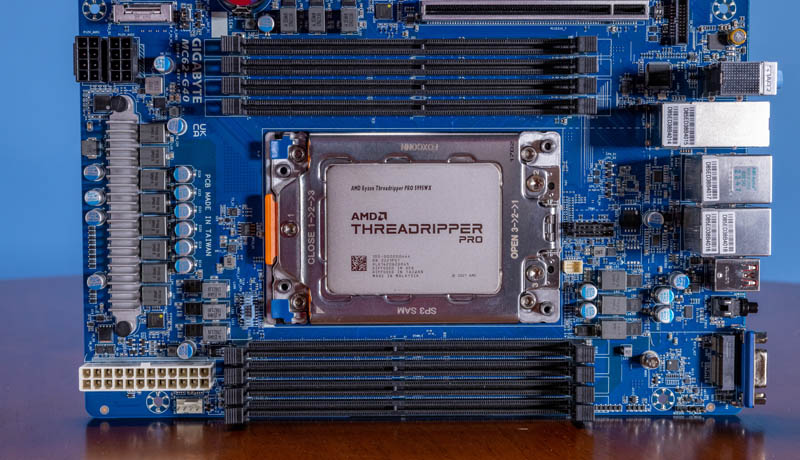
You can see our video, including this motherboard, here:
In addition to the higher core count CPUs, one can use up to eight DDR4-3200 ECC LRDIMMs/ RDIMMs for up to 2TB of memory capacity.
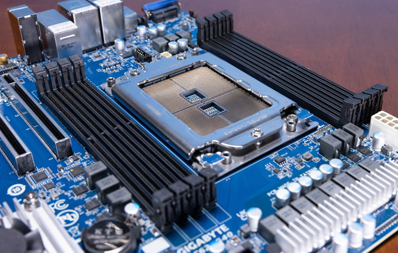
These DIMM slots extend to the top of the motherboard, so the power inputs and components are on the right side of the motherboard. Gigabyte keeps them out of the airflow of the CPU and aligns the power inputs to be in front of the DIMM slots that require lower airflow.
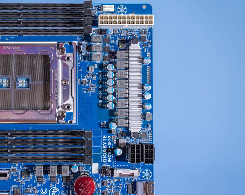
Perhaps where this motherboard shines is in its expandability. There are seven PCIe x16 physical slots. Six of these are PCIe Gen4 x16 electrical, one is a x8 electrical slot.
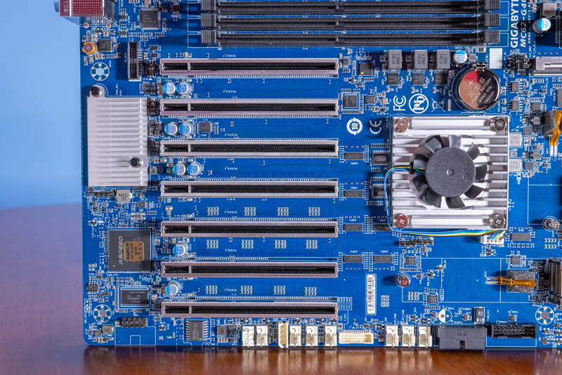
One other feature you may have seen is that there is not just the CPU fan header near the power inputs but there are eight system 4-pin PWM fan headers. These are all at the bottom of the motherboard and that may mean one needs longer fan cable runs to reach them.
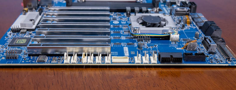
Along the bottom, there is also a M.2 2280 (80mm) slot for internal storage.
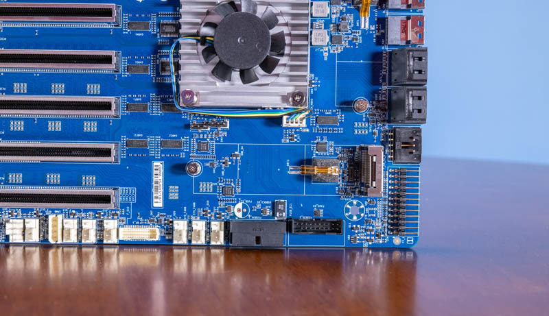
There is a second M.2 slot next to the WRX80 chipset.
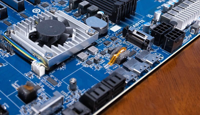
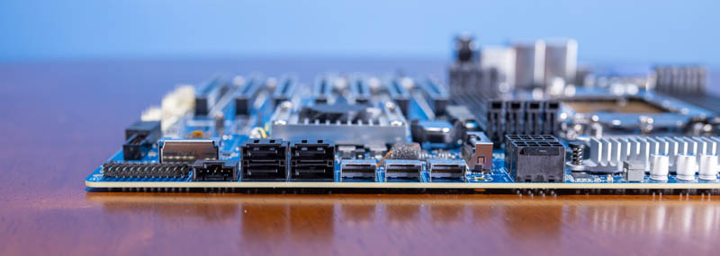
Most of the drive and front panel connectivity is via connectors parallel to the motherboard. There are four 7-pin SATA connectors and three SlimSAS connectors. These SlimSAS connectors can each provide a PCIe Gen4 x 4 link, often for a NVMe SSD, or 4x SATA III ports for additional SATA storage.
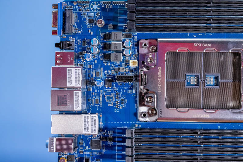
On the rear of the motherboard, we get rear I/O that looks like a cross between server and workstation I/O. There is a VGA port as well as a chassis ID button. In addition, there are four USB 3.2 Gen2 ports. There is another block, however, with USB 3.2 Gen2 Type-A and Type-C ports. We also get three audio jacks.
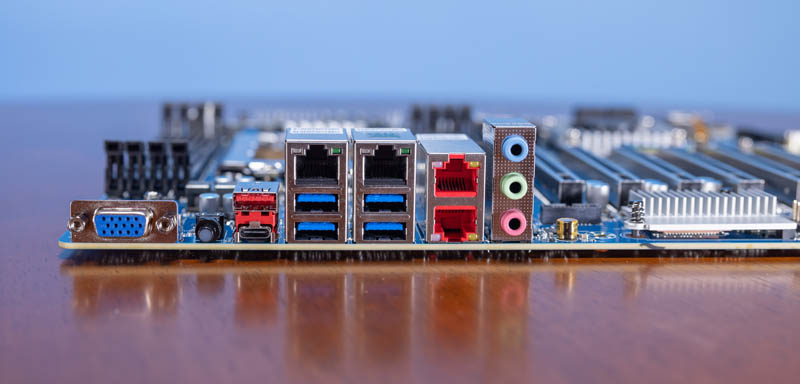
On the networking side, we get an Intel i210 LAN, a management LAN, and two 10Gbase-T ports. These 10Gbase-T ports are powered by an Intel X550-t2 that is on the motherboard under a small heatsink.
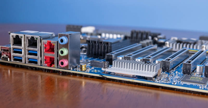
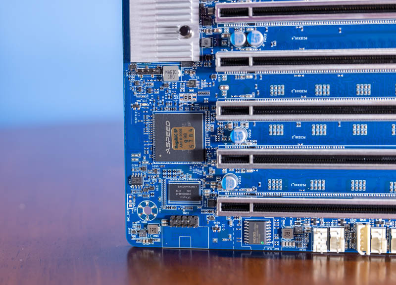
The out-of-band management port connects to the ASPEED AST2600 BMC.
One other small item is that between the CPU and the rear I/O blocks there are two features. One is a TPM header. The other is a M.2 2230 WiFi slot. This board does not come with WiFi, but there is a designated slot if you wanted to add it.
That is a lot, so let us get to the topology to see how it is all connected.


The system diagram in your article does not match the diagrams in the motherboard manual or the W771-Z00 server manual. Both show all three SlimSAS ports connected to the WRX80 chipset.
The first two PCIe slots (close to the CPU) should be spaced for double-wide cards, the board would have been only 1.5 or 2 inches bigger. Possible the traces would be too long though for PCIe v.4. Nice board nonetheless!
I noticed a barcode on that “unique password” sticker. Has anybody tried scanning it into a password prompt?
Jay: No, the PCIe spacing is fine. If you want to lose slots, buy a consumer board for that! Some of us need the extra I/O slots for other hardware.
Hello Lalafelon: For the sake of clarity, Jay Kastner never suggested the giving up of available PCIe slots, only that the inner spacing for slots 1 and 2 be increased to accommodate double width cards, retaining the same 7 PCIe slot count, and the footprint of the PCB could have been made larger than CEB format. I have seen such double PCIe spacing on other “server/workstation” boards, or to be more descript, on high physical slot count and, or high phisical resource demand configurations, to reverse placement order such as that seen on the Supermicro X11DPG-QTo. I make use of 11 active PCIe slots, of which some PCIe slots are off loaded onto my own custom made backplane assembly with 10 additional, single width, PCIe slots (6×16, 4×1), fitted into a 1 of, factory custom made CaseLabs Twin STH10 case with matching twin pedestals. The workstation motherboard configuration makes use of twin double wide PCIe for both slots 1 and 3, slots 2 and 4 left vacant, plus have x2, 12G RAID Controllers with 4GB cache each, and x4, 12G RAID Expanders (off loaded from motherboard), hosting 68 hot slot drive bays. Would you, per your experience, stigma rate the above mentioned rig a “consumer” based motherboard system, and at the time of completion ranked near the top, <2%, for the CPU class, just because it makes use of double width slots, like that seen on some gaming systems?