
Something that one getting into fiber will run into, and that is very different than in the world of copper-based networking is APC versus UPC. Depending on the type of fiber you are using, you may see either, and putting them together incorrectly can mean damaging cables. So this is an ultra-important concept, but we are also going to give some easy guidelines to help you spot both.
APC and UPC What Does This Even Mean?
First, let us get a few terms out of the way.
- APC stands for “Angled Physical Contact”
- UPC stands for “Ultra Physical Contact”
These are the two we are going to focus on today. If you are running modern OM3, OM4, OM5 multi-mode cable or OS1/ OS2 single-mode fiber optic cable, you are likely going to be using either UPC or APC (more on that in a bit.) There is another standard called just PC for “Physical Contact” that was used in older cables in the OM1 and OM2 generations. These days, you are going to see UPC or APC on new fiber connectors that you install, but it is very important to understand the difference.
The Big UPC versus APC Difference
Here is a quick diagram in terms of the difference between the two polish types.
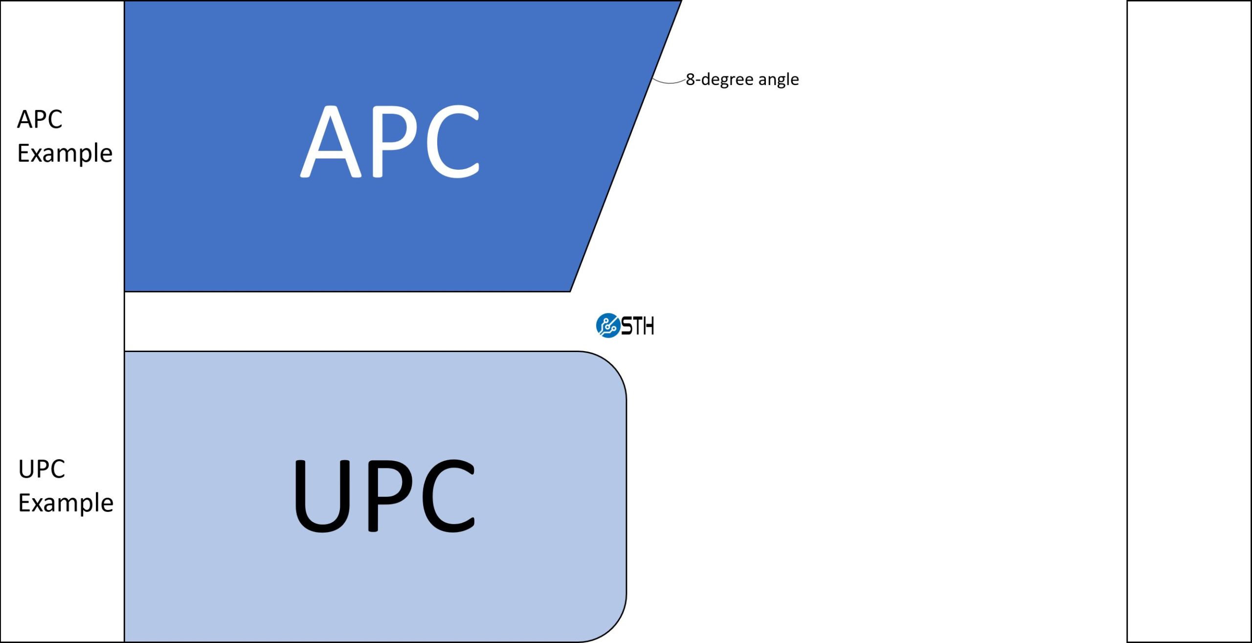
We have to remember here that the goal is to mate two strands of fiber and continue to transmit light (data) over that mating.
UPC as one can see has a slight curvature for better alignment. They may look flat, but they are actually slightly curved for that. The key challenge is that light can reflect off of the end of the end face and will travel back through the fiber optic cable towards the light source.
APC on the other hand is polished at an 8-degree angle. That may not seem like a lot, but that angled edge changes how light is reflected back. With the 8-degree angle, light that reflects off of the end face is directed toward the cladding around the fiber optic cable instead of more directly back to the light source as we would see in APC. This means we usually get less return loss with APC.
Given the different connector angles, one should not try to connect APC and UPC cable together. The goal should be mating a flat-ish UPC to another flat-ish UPC or angled APC to APC. As one may imagine, not only is there a potential for loss, but damage can also occur if one attempts an incorrect mating.
Caution, Potential for Damage!
If you see the above, you may have realized the challenge this can pose in the field, or simply when trying to build a fiber infrastructure. The pointed end of the APC face plate is very small. A good mental model is to think of a multi-mode fiber core as roughly the same diameter as a human hair. A single-mode fiber optic core is 9 micrometers or significantly smaller in diameter than a human hair. Still, with the core, cladding, and so forth, we generally just use the concept of thinking about a fiber strand as being about the size of a human hair. As a result, an 8-degree angle for the APC polish leaves a leading glass edge that is relatively thin.
There is basically the rule:
- UPC to UPC is good
- UPC to APC is bad
- APC to UPC is bad
- APC to APC is good
- Aligning APC to APC incorrectly is bad
Here is the conceptual diagram of these rules:
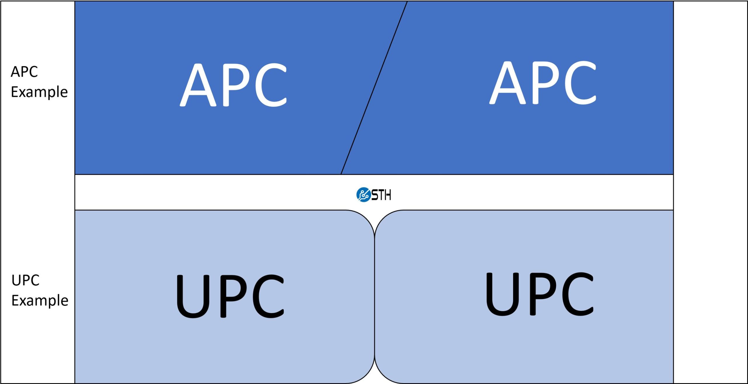
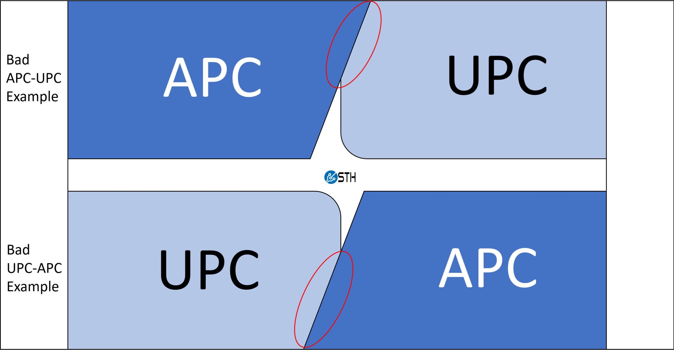
It is important to mate these ends correctly so that one does not damage cable and connectors. If there is a chance for damage, one may wonder why even have APC. That comes down to loss.
Key Loss Stats for APC, UPC, and PC
Although we are mostly focusing on APC and UPC here, we are going to include PC as well.
- UPC return loss should be -50db or greater
- APC return loss should be -60db or greater
- PC, the older standard, has a return loss of -40db or greater
Return loss is a measurement of reflected light, or in simpler terms the amount of light that does not make it through the connection and is instead reflected back into the cable. This return loss figure is expressed as a negative dB value (-XXdb.) Perhaps the easy way to remember this is the “-” is loss, so the higher number after the negative sign is a smaller loss.
A Trick for Telling APC versus UPC Polish
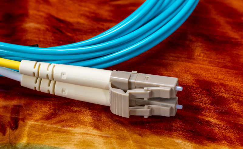
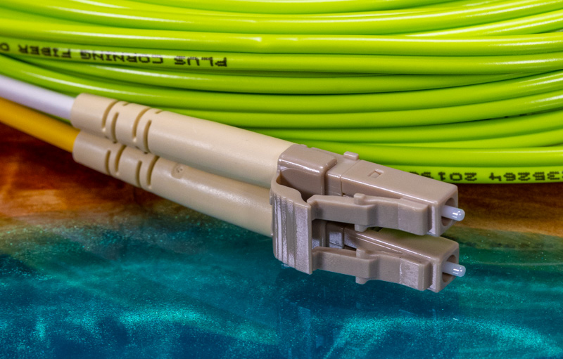
The easy trick for being able to tell if a connector is using APC or UPC is to look at its color. The industry realized that with potential incompatibility and potential for damage, there needed to be an easy way to tell the two polishes apart. Typically, one will see green connectors for APC and blue/ teal connectors for UPC. Here are examples of MTP connectors:
Looking here we can see the yellow OS2 single-mode MTP cable having green latches signaling that we have an APC face. We also have a pink OM4 cable (OM4 is usually either teal like OM3 or pink) with a teal latch telling us we have a UPC face.
Since we are focusing on MTP cables for this series as that is the higher-end and less understood option, we are going to discuss with that lens. Generally, one will also see OS1 and OS2 single-mode fiber using APC, and multi-mode OM3, OM4, OM5 fiber using UPC, but it is always best to double-check cable specs and the connector as well. With lower-density simplex/ duplex cables, there is more variation.
Final Words
If you are installing fiber, we are generally suggesting folks skip OM1, OM2, and OM3 for multi-mode and just install OM4 (OM5 that is lime green is still pricey at the time of this writing.) Installing OM4, we also suggest UPC since that ecosystem is largely UPC. If you are installing single-mode fiber then you will often see APC on the LC and SC connectors but there are certainly UPC there as well. For single-mode MTP, you are likely to see APC being used. Especially in long runs and with service providers bringing service to a building it is common to see bundles terminated to MTP using APC and then connected into patch panels. Lower loss makes less of a difference on a 10m cable, but on a 10km run, it can have a huge impact.
The key here is to ensure you are mating UPC to UPC, APC to APC, and when mating APC, ensure you have the proper orientation. We have seen some folks online get “creative” trying to mate female-to-female MTP cables and only to find they damaged cables trying to incorrectly mate two APC ends.
We hope this at least helps understand what it means when you see APC and UPC listed for fiber optic cables, and what to look for.


Out of curiosity, is it viable(either by visual inspection with a basic loupe, or by means of test equipment short of the full, powerful but pricey, Fluke thing that fiber techs pull out to analyze a link) to determine the polish type of an unknown fiber; or is this one of those situations where color coding is the only realistic option and anything in the ‘unknown’ pile must forever be distrusted?
I don’t like inheriting good old rat’s-nest-topology networks, so it’s not a situation I’d prefer to have to deal with; but if there is a good way to verify an unknown rather than throwing stuff away(especially if it involves re-pulling) that would be quite handy.
Thank you for posting these introduction to fiber articles. These articles are what I was looking for last year when I was starting to move to fiber in an office; too bad it wasn’t around at that time. I spent tens of hours just figuring out that I needed to use LC connectors because it seems like every single device that uses them just assumes that people know you need a cable with LC connectors and doesn’t post anywhere in its documentation that it has an LC socket. I didn’t even know about this APC vs UPC difference until today, so I guess I just got lucky when picking cables and connectors since the network works properly.
Well done thanks. So I plan on continuing to use OM4 UPC LC fiber patch cables for my SOHO Network. All works well with 10Gb to 1Gb gear.
I’d consider covering fiber polarity and keying in the APC section. You talk about misaligned APC connections, but not how they might occur…. Maybe this is covered elsewhere? The copper world has polarity, which it largely ignores as it’s normally not important. Not so in fiberland….
MTP vs MPO? You’re using the ™ in preference, and there might be a good reason (there are some advantages), but spelling it out would seem like a good idea.
“This means we usually get less return loss with APC.” – this is a confusing statement. “less return loss” could well mean “more return”, but that is not what is meant here. This is a common way of speaking about return loss, and it confused me for quite some time. Lower transmission losses due to less returned/reflected signals, or lower returned (rejected) signal. Is there equipment that can be damaged by reflected signals that would make APC a better choice? I note there’s generally not a difference between the max loss ratings on most couplers I’ve seen, so I’m wondering to what extent the extra order of magnitude is helping. I’ve also heard that UPC connections degrade quicker than APC (connect/disconnect cycling, obviously not in operation), but I’m not sure to what extent that’s really true.
David, we are building this out on a regular basis. Those are other subjects we will be covering.
I’m looking forward to it, been great so far, thanks Rohit!
One of the main users of APC polished connectors are Passive Optical Networks(PON). An Optical Line Terminal (OLT) port sends signal down to 16, 32, or 64 user OLT (Optical Line Terminal) ports via an optical splitter/combiner somewhere in between. Each user OLT port has to send upload signal back at different distances which means varying signal strength and the refelections of 64 different signals. The optical prism in the path also induces some loss. So reuturn signal loss becomes important when splitting light at 10 to 15 miles distance to as many as 64 ports.
Most SFP modules used in switches and gear are designed for UPC since they are direct connected and loss is less of an issue. However, there is not really a downside to using APC if supported. And often, the long run will be APC to a patch panel on the back, and UPC on the front to the gear. Using a cable with UPC on one end and APC on the other is fine, as long as it’s the same connector polish being mated together. And in most cases, it’s always Multi-mode to Multi-mode and Single Mode to Single mode.
I like to use OM2 for 1gbps fibre links, it colour codes my links, orange 1gbps, aqua 10gbps and magenta 40gbps etc.
N.b. in Germany there’s another angled connector coloured magenta, which has – of course – a different angle from APC. It is mainly used by Germanys telco company Deutsche Telekom.
Thanks for your very clear explanation.
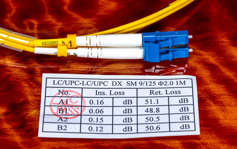
One typo in the sentence under the picture of upc testing label it should say “UPC” instead of “APC” for back reflection.
Thanks for highlighting the importance of APC and UPC in fiber connectors. I didn’t realize how critical it was to ensure correct installation and testing. Your post has given me a better understanding of what to look out for when setting up our fiber network. Great job breaking down the technical details in a clear and concise manner!