Here is a fun one from Computex. We have been discussing how difficult it is to fit full sets of DIMM slots in servers with modern 12 DDR5 channels per socket and 2 DIMMs per channel (2DPC) designs. One challenge is getting 2DPC to work with 24 DIMMs attached to a socket. The other challenge is the space involved. The Gigabyte R283-ZK0 is a dual AMD EPYC SP5 server that manages to twist its DDR5 layout to fit in a standard 2U width.
Gigabyte R283-ZK0 at Computex 2024
The front of the Gigabyte R283-ZK0 looks like other servers, except that it has only eight front NVMe bays and then a big fan wall.
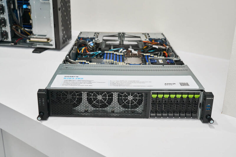
With the lid off, we can see a CPU slot in the back, in front of some PCIe risers.
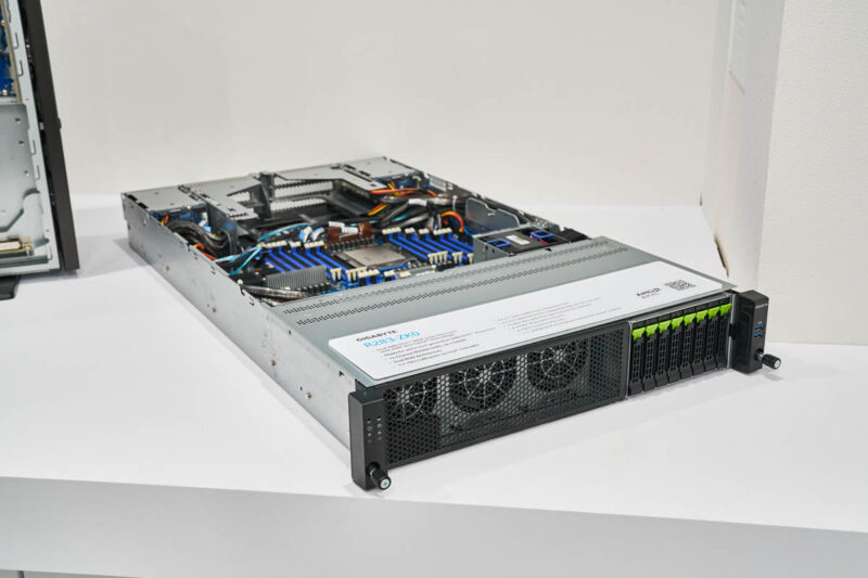
Looking above the system, we can see just how crazy this motherboard gets. There are 24 DDR5 RDIMM slots per CPU. In a dual AMD EPYC 9004 SP5 configuration, that is a total of 48 DDR5 RDIMM slots.
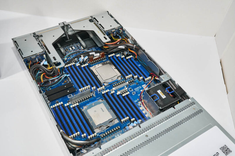
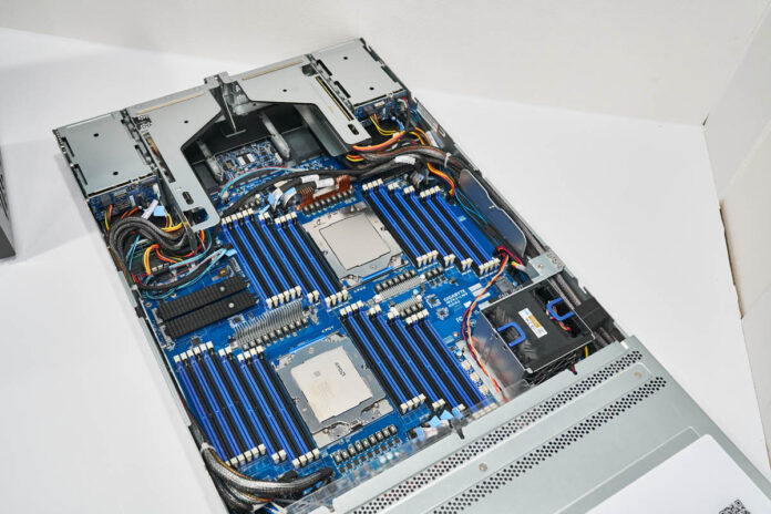
To fit this many DIMMs, the CPUs cannot be aligned next to one another. Instead, there are stagger sets of 6-2-4-4-2-2-4 DIMM slots. The slots are twisted on the motherboard at an angle to allow for some overlap of the slots and sockets.
Final Words
In 2023, we published Why 2 DIMMs Per Channel Will Matter Less in Servers. This is a great example of why that configuration is so challenging. While one gets 48 DIMM slots in a motherboard, the two CPU sockets take up a huge amount of depth in the server, to the point that the rear I/O risers start to get atop the DIMM slots. While 12-channel CPUs are great for memory bandwidth, capacity is more challenging and that is why we see few designs taking on the challenge in dual-socket servers. It is easy to see how the 24 DIMM slots and a CPU socket take up well over half of the width of the chassis.
For those of us who love servers, it is fun to see the slots take a twist!


“modern 12 DIMMs per socket and 2 DIMMs per channel (2DPC)” I assume you mean 12 channels per socket.
While rare, bigmem machines are still required in various roles. Would love to see a server like this to come with 8x512GB CXL on top of 48 dimms, plus some additional nvme as swap.
This system seems like a particularly dramatic example, since they’ve had to go nuts with board area(and probably some genuinely alarming serpentine traces to get all the lengths to work); but I’d be curious for more general cases as well: with the rise of cabled PCIe risers and the pretty dramatic increases in cores per socket, per-core performance, and TDP per socket; is there much activity in vendors building motherboards to fit the smallest possible chassis, mostly 1U, sometimes 2 as in this case; but then doing sheet-metal-and-fans variants to accommodate customers who either want lots of PCIe slots, lots of in-chassis storage; or who simply can’t accommodate the power and cooling demands of filling racks with modern 1Us; but would rather have power savings from bigger, slower, fans instead of just screaming 1Us surrounded by blanking plates(those are certainly the boring customers; but with the ‘server consolidation’ potential of contemporary platforms probably fairly common ones; plenty of them operating servers out of various little edge closets and things where power, thermals, and noise are constraints that cannot be economically changed)?
It doesn’t seem like those versions(especially the last) would be the exciting ones you would lead with at your trade show booth; but if all the really expensive motherboard engineering is kept identical across the variants it seems like that might control the cost of offering more specialized chassis types by making the changes mostly mechanical; rather than involving substantial reworks of the motherboard as would have been the case back when all the PCIe peripherals slotted directly into a motherboard connector(whether standard or proprietary) and so any chassis layout change meant a motherboard layout change.
The pendulum will come back.
We will see daughter cards for memory and slotted CPUs again.
Board real estate cannot be sacrificed like this given the way the signals need to stay in sync/parallel.
The reason I think this will happen is that core density will only keep increasing.
To keep those cores working more memory load will be required. A side to that need will be L3 cache increases as the cores need to be fed immediately.
Not keeping them fed is very expensive both in power and in lost processing cycles when at idle.
This is just a hint of what can be accomplished if you relax placement constraints and let a computer optimize placement and routing at the same time.
“We will see daughter cards for memory and slotted CPUs again.”
Honestly, I can’t see that happening. With now even the GPUs having to move to socketed designs for cooling as much as bandwidth, future higher-core count CPUs moving back to slot mount seems extremely unlikely.
How long until we see 2U systems with the motherboard mounted halfway up, with DIMM sockets on the top and the bottom? It’d make servicing a pain, but I doubt that really matters.
The 19-inch rackmount form factor seems to be reaching its limits. They’re almost out of room. I wonder if we’ll soon see a switch from 19-inch to 24-inch rack units. It seems inevitable that might happen, and even then it still may not be enough. @Philip Elder may be right. We might have to start re-designing boards to function more like backplanes again, with the memory on separate daughter boards plugged into slots and the CPUs clustered together on their own baseboard connected to the memory backplane. There’s just no other good way that I could see that many channels of memory fitting in such a rack unit with the typical 2 DIMMS per channel layout we’re using. Something’s gotta give somewhere.
Of course, another possible solution might be to re-think how memory connects to the CPU and how the CPU addresses and accesses the memory modules. We might need to switch to a multilane PCIe-like serial bus in place of the current parallel ones we are using. In this model, the memory modules have multiple local parallel channels on-module. Each module would have its own local memory controller, or LMC, which connects between the CPU and the RAM chips on the modules.
The CPUs would connect to the LMCs via the multilane serial DRAM bus and the LMCs would mediate the communications between the CPUs’ serial memory host interface and the local on-module parallel memory I/O channels, acting as a signal repeater and translator for the CPUs.
An example layout for 24 channels would use six modules, each with four local memory channels and its own LMC. The CPU memory host bus could have, say, 32 lanes, supporting up to 8 separate serial channels at each CPU. Each serial channel consists of 4 lanes. Each lane will support up to 32 on-module channels, split across a total of 8 modules. This would allow for a grand total of…
4 on-module RAM channels x 8 modules = 32 RAM channels per serial memory host channel at the CPU.
8 serial memory host channels per CPU x 32 RAM channels = 256 module-level memory channels, split across 64 total memory modules.
Since we are only needing 24 memory channels, we need only 6 quad-channel memory modules per CPU, thought in reality we could max that to 8 modules. This would allow for 32 total memory channels using quad-channel DDR-whatever RDIMMS. The LMCs on each memory module would take care of the communication interface between the CPUs and the memory chips themselves. It would also potentially address the sync issues since the CPUs aren’t using a parallel host I/O link to the RAM, that’s now a multilane serial bus instead.
Theoretically, a 48-DIMM system could be condensed down into just 12 physical modules, six per processor, using this model and this in turn would alleviate some of the space constraint. Yes, it would mean an extra chip (the LMC) between the RAM and CPUs, but I believe this could work well enough. But then again, I’m not a system design engineer and somebody else might have a better idea than mine.
@Stephen Beets – to see what you’re suggesting in action, look at IBM Power 8, which used the Centaur chip as your LCM, a high-speed serial Axion bus to the CPU (same bus used for interconnect as well), and standard DRAM channels from Centaur to the DIMMs.
Find a detailed description here: https://research.ibm.com/publications/the-cache-and-memory-subsystems-of-the-ibm-power8-processor
@Scott, for 2U they have come up with double height MCRDIMMs, see articles at Tom’s and Anand.
“Micron demonstrated one ‘tall’ 256 GB DDR5-8800 MCRDIMM at GTC (pictured) but also plans to offer MCRDIMMs of standard height for applications like 1U servers. Both 256 GB MCRDIMMs are based on monolithic 32 Gb DDR5 ICs, but the tall one places 80 DRAM chips on both sides of the module, whereas the standard one uses 2Hi stacked packages, which means that they run slightly hotter due to less space for thermal dissipation. In any case, the tall module consumes around 20W, which isn’t bad as Micron’s 128GB DDR5-8000 RDIMM consumes 10W at DDR5-4800.”
That solves capacity, but doesn’t make the coming 32 DIMM slots (per CPU) take up less space.
I suspect that placing DIMMs on both sides of the motherboard would lead to crosstalk problems, not to mention the need for finer traces to run to the DIMM areas. If it were practical I suspect we would have seen it become popular already, if not only to allow more memory for tiny motherboards.
CAMM and DDR6 may also solve the capacity problem, though not the real estate issue, but those won’t be coming before MCRDIMM. Some genius might try rotating the CPUs 90° only to discover that doing so affords the tiny bit of extra space needed.
SODIMMS!
@David Freeman
Thanks. I kind of figured somebody already did something along the lines of what I outlined.
Unfortunately, the link you provided goes straight to an “Error 404: Page not found” on IEEE’s site. And since they don’t let you read full research papers without an account and paying them stupid money, I couldn’t have read it even if it was available. But, yeah.
I’m surprised that line of thinking HASN’T been more widely adopted. Why has only IBM thought of this and why only with POWER8? Surely ONE other company has thought of the same idea that I had, or that IBM had.
One of the newest layouts seems to be Gigabyte’s H253-Z10-AAP1, where each node has the memory and processor turned to a 45° angle; resulting in 24 channels per node, or 48 in a 2 CPU 1U.